Guys it’s past my bedtime, I feel bad for abandoning this right now when you’re trying to help me , up at 5am and a hard day ahead, sorry.
D1 and D2 are diodes, not resistors. But at least that shows us the base pins of Q5 and Q6 are getting the right voltage.
I still want to see the voltage across R8, and then R11. Just trying to figure out if this FE is even alive. Not sure how to make it more clear.
I still want to see the voltage across R8, and then R11. Just trying to figure out if this FE is even alive. Not sure how to make it more clear.
Attachments
Last edited:

With the board detached I’m able to adjust the P2 pot but when the board is connected and my dmm is connected to a resistor attached to the output transistors nothing is happening when I turn the pot .

So at least the IPS and VAS are alive on this front end. There will be a difference of potential (DC voltage) between "+D" and "-D" (labeled on schematic), and P2 will adjust this amount. I don't know what a "nominal" value is for that to start waking up the output stage transistors. Obviously everything has to be wired properly and no parts are defective / shorted. I've never had my hands on a real Stasis. Hopefully someone else will chime in.
voltage between D+ and D- is?
and - is it variable, while fiddling with trimpot?
that test possible even without OS connected to D+ and D-
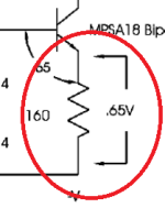
in between those points is biasing generator for OS bases
and - is it variable, while fiddling with trimpot?
that test possible even without OS connected to D+ and D-
in between those points is biasing generator for OS bases
I measure the voltage on the D+ & D- when I get home from work.
My instructions were to set the P2 pot at maximum resistance before start up and then slowly increase the resistance upon powering on , I have my dmm on a 1ohm ( number 9 ) resistor on the positive side , I was then supposed to turn the P2 pot slowly to bring up the bias but nothing happens.
My instructions were to set the P2 pot at maximum resistance before start up and then slowly increase the resistance upon powering on , I have my dmm on a 1ohm ( number 9 ) resistor on the positive side , I was then supposed to turn the P2 pot slowly to bring up the bias but nothing happens.
Just so we are clear. Remember when measuring this 1 ohm resistor in the output stage, we want the measurement ACROSS it. One voltmeter probe on one side, other probe on the other of the resistor (not ground or somewhere else). If we know the value of a resistor, and we measure voltage across it, we can then figure out (using simple ohm's law) how much current is flowing through it. If you know two values we can calculate the third.
I=E/R
R=E/I
E=I*R
It's critical to know what this value (the current flow, amperage) is to make any of these projects work, and work properly. The idea with an amplifier output stage is to start with no / or very low current through the output transistors, and then slowly wake up this sleeping giant. With time and patience you eventually will have the amp idling at the prescribed current through the output stage (proper P2 adjustment does it), and very low DC offset at the speaker terminals (proper P1 adjustment does it).
D+ to D- measurement - One voltmeter probe on D+, the other voltmeter probe on D- (not to ground, or power rails, or somewhere else). You should see that voltage increase or decrease as you spin P2. OS does not have to be connected as ZM mentioned, to see the behavior.
Last edited:
i remember having a hard time getting mine started up on the first go. I had to fiddle w the offset and bias a little to get it started, then it took many hours of adjusting both till i was able to get the amp running in a stable manner
Just to expand on #273 a tiny bit.. the way it works is:
D+ to D- voltage is high = output stage current is high
D+ to D- voltage is low = output stage current is low
So obviously start "voltage low" as already stated, before trying it with the output stage. Don't want "pedal to the metal" on start-up...
D+ to D- voltage is high = output stage current is high
D+ to D- voltage is low = output stage current is low
So obviously start "voltage low" as already stated, before trying it with the output stage. Don't want "pedal to the metal" on start-up...
Ok D+ and D-
The voltage does change when I turn the pot .
But voltage at resistor does NOT change

Zero volts on resistor…

The voltage does change when I turn the pot .
But voltage at resistor does NOT change
Zero volts on resistor…
Last edited:
Assuming wiring is correct and no defective components, there will be a threshold where the output transistors will start conducting (passing current). No current will flow until you reach that point. I don't know what that magical voltage is (from D+ to D-). As I said I don't have one of these.
Yea i made that mistake and fried a couple ZTX transistors on my buildJust to expand on #273 a tiny bit.. the way it works is:
D+ to D- voltage is high = output stage current is high
D+ to D- voltage is low = output stage current is low
So obviously start "voltage low" as already stated, before trying it with the output stage. Don't want "pedal to the metal" on start-up...
- Home
- Amplifiers
- Pass Labs
- Help please with my poorly Stasis 2