Hi, this is probably a basic question but please help if you can.
I have a transformer that is center tapped 10v 0 and 10v secondary windings. (I don't have a scope, but lets assume they are out of phase, I will confirm before I build)
I want to make a 20v DC unipolar power supply.
I was going hook the 10v and 10v up to the ac side of a bridge rectifier, then at the +/- side of the bridge rectifier put big capacitors there to smooth out the signal.
If its a 10-0-10 transformer (so essentially three wires) then what you describe is correct.
If its a 0-10, 0-10 tranny (so totally separate windings, four wires in total) then the phasing does matter. In that case simply join one end of each together and measure the AC voltage across the free ends. If its correct you will have 20 vac, if incorrect it will be near zero... in which case you reverse just one winding.
If its a 0-10, 0-10 tranny (so totally separate windings, four wires in total) then the phasing does matter. In that case simply join one end of each together and measure the AC voltage across the free ends. If its correct you will have 20 vac, if incorrect it will be near zero... in which case you reverse just one winding.
Thank you so much, here is a follow up question.
The 20v supply is for a power amp. The preamp runs off 9 volts, but 10v is close enough. Can I make a second supply at 10volts off the center tap? I do expect the preamp to draw much much less than the power amp section, or my other thought was just a voltage divider?
The 20v supply is for a power amp. The preamp runs off 9 volts, but 10v is close enough. Can I make a second supply at 10volts off the center tap? I do expect the preamp to draw much much less than the power amp section, or my other thought was just a voltage divider?
You need first of all to understand the relationship of AC voltage to rectified DC. Your 20 volts AC will give a DC voltage (as measured across your big cap) of around 28 volts, maybe a little higher at light loading.
Vdc = Vac * 1.414
Because the negative end of the big cap will become audio ground (I assume), it means the centre tap is off limits. What you should do is use a simple 3 legged voltage regulator such as the LM317 for your 9 volt supply. That would give a super clean and stable supply. I've attached the data sheet (you would be fine with the standard LM317, it doesn't need be the AHV version).
The output can be adjusted to any value you choose.
Attachments
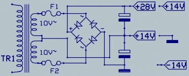
You cold do it like this.Depending on witch connection goes to the groundThank you so much, here is a follow up question.
The 20v supply is for a power amp. The preamp runs off 9 volts, but 10v is close enough. Can I make a second supply at 10volts off the center tap? I do expect the preamp to draw much much less than the power amp section, or my other thought was just a voltage divider?
it is a symetrical supply or a simple-double voltage out.
Mona
Attachments
Thanks Mooly and Ketje for the help. Yes I tested it (I'm waiting to get oscilloscope in the mail) It ends up being 26.5v DC. I really like that LM317. That is nifty. I'm sure I will end up using that in the future. I used a voltage divider with resistors 4.7k and 2.7k and ending up measuring about 9.5 volts. Its a simple preamp I was powering with a 2n3904. The resistance the battery sees was between 68k and 115k depending. So I shot for a voltage divider an order of magnitude lower in resistance (or higher in current) so the load wouldn't effect it much. It worked very well, but of course isn't very efficient. Its basically a distortion with gain control which will go into an amp. I need to make a buffer going to the amp, and have a lot of trouble getting op amps to work right. I will repost another topic or look through some. I made such a basic op amp buffer with a battery and I can't understand why it doesn't work. But I will post this in a different section I think. I have such a hard time getting op amps to work right for me. That's why I'm using transistors. I may make a jfet buffer, I think that would be hard to mess up.
- Status
- Not open for further replies.
- Home
- Amplifiers
- Power Supplies
- Help please. Want to make unipolar power supply from center tapped transformer