Zen - I already put it in post #30 🙂
I did saw it , however I was looking for voltages at important nodes .....
though , me not exactly seeing something is sorta normal thing, geezer, blind, lazy ...

Please measure voltage at top of R20 and the left side of C9
Top of R20 is 1.49 V
Left of C9 is 0.77 V
Thanks!
Ok , Wayne already did all the job needed
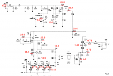
pic pulled from pdf (one you can find linked few posts above) and I did mark with red all voltages
compare with yours , if something is different - mark on pic with different color and post here
+/-10% differences are normal and OK , everything higher than that can be suspicious
ZM: I'll do this later today and post. Thanks!
I see you posted earlier that the voltage was 28.5 at R8, so the voltage is about 28 volts across R14. Q4 appears to be in saturation. Points to around Q6 if I'm thinking correctly?
R14 should be pretty warm. V*V/1K
R14 should be pretty warm. V*V/1K
Last edited:
Problem seems to be around Q6. What's the voltage across R14, 1K resistor.
Measuring to ground:
R14 top 28.3 V
R14 bottom 0.78 V
= 27.6 across
R24 (100K) measures 1.6K in situ. It is clearly marked 100K. I realize it should have one lead desoldered to accurately measure, but before I do that, is it suspicious to measure that far off?
The Gate to Source of Q6 should be a high impedance, so you should see the 100K with an Ohm meter.
Make sure there is no voltage present.
Q6 is a dual package Jfet with each Jfet in parallel.
Odd with both channels the same?
Here is the schematic with annotations of the voltage I measure at each of the nodes. I'm showing the left channel, but the right is very similar. Yes, I think that's strange. The issue does seem to be around Q4 and Q6. For the 2sk170 devices, the voltages are higher, but I have two 47k resistors at R27 instead of one.
Attachments
everything is OK , except Q6 - 2SK389
check visually and with ohmmeter both R24 and R25 ( even if 30mA through Q6 can't be explained with malfunction of any of these, except in case that 10R is totally zeroed and you have highish Idss 2SK389 there ..... )
pull them 2SK389 out and check with simple matching jig
use 9V battery if that's most convenient
edit: worth checking - is there any space left between R25 body and top GND grid/mask ...... possibility of shorting resistor body to GND and messing with its resistance...... as much it is sound impossible, I stumbled on that in my service practice
if needed , 2SK389 is easily replaced with pair of properly matched 2SK170BL ( I mean , BL preferably)
edit: regarding 10R of R25 .........if it's shorted - in that case you couldn't have there 0,3V ...... so 10R still must be 10R
Attachments
Last edited:
everything is OK , except Q6 - 2SK389
check visually and with ohmmeter both R24 and R25 ( even if 30mA through Q6 can't be explained with malfunction of any of these, except in case that 10R is totally zeroed and you have highish Idss 2SK389 there ..... )
edit: worth checking - is there any space left between R25 body and top GND grid/mask ...... possibility of shorting resistor body to GND and messing with its resistance...... as much it is sound impossible, I stumbled on that in my service practice
edit: regarding 10R of R25 .........if it's shorted - in that case you couldn't have there 0,3V ...... so 10R still must be 10R
Thanks for the suggestions. There is enough space under R24 and R25 to slide a piece of paper.
I can measure 25 mA through R25 and 4.9 mA through R24.
Everything looks fine with R24, R25 and Q6.
Which leaves Q6. I will pull and test tomorrow.
everything is OK , except Q6 - 2SK389
pull them 2SK389 out and check with simple matching jig
use 9V battery if that's most convenient
if needed , 2SK389 is easily replaced with pair of properly matched 2SK170BL ( I mean , BL preferably)
Measuring the 2sk389BL with a 9V battery and the schematic for a N-channel device, side 1 measures OL and side 2 measures 8.3 mA. On the second device, side 1 measures 10.3 mA, but side 2 measures OL. I believe that means I'm SOL, right?
I also see by searching the forums for "2sk389" and "Pearl" that I'm not the first to blow a 2sk389.
And of course that a replacement is not so easy to come by, although MojoTone is selling them for $18 a pop. I don't have any 2sk170BL devices, but I do have some matched 2sk369BL devices with an IDSS in the 8 mA range. Can I substitute these if I replace R25 with a 20 ohm resistor? Or am I better off buying lsk179's?
Thanks for all the help.
Buy the LSK170B pairs.
You probably want to replace the ZTX450s as well.
EDIT: I'm sorry, it didn't register that you have the 389s on hand. I think those would work beautifully as-is.
You probably want to replace the ZTX450s as well.
EDIT: I'm sorry, it didn't register that you have the 389s on hand. I think those would work beautifully as-is.
Last edited:
use one 2SK369BL instead of 2SK389 (practically 2SK369 is as two JFets of 2SK389 in parallel) ; you'll manage with pinout
adjust value of R25 to have approx. 5mA through JFet, if needed
as 6L6 said - good to replace ZTX, too
adjust value of R25 to have approx. 5mA through JFet, if needed
as 6L6 said - good to replace ZTX, too
any news?
I didn’t have any Zeners, so I ordered. Should be here Tuesday.
Hi, I'm the one that bought Pearl from jamayfie and waiting for its return if all goes well, I'm sure it will. I thought while we wait for part to come in and be installed I could ask you guys that know this preamp a few questions while I have your attention I've never heard a Pass Preamp and thought it would be interesting to try a DIY Pearl. I've heard a few numbers for gain from 30 to 40 does anyone have an opinion what it is? Can gain be increased and if so how much can achieved without causing problems. If so what needs to be done. Most important what do think of how it sounds and does it compare to any of Pass Labs commercial phono preamps or other brands or dollar amount the Pearl competes with, thanks
- Home
- Amplifiers
- Pass Labs
- Help, Pass Lab Pearl 1, gain is gone both channels