fter building Many Amps From Here and the Net I decided to make my own DesignCalled (Sound Boy)😎 My First One!
it is a made from ideas from various shemetics from the net
reson being I have no money to buy recomended books
to teach me to design as they are very costly here
were I leave (South Africa) R1000.00
I can build Circuits, Make my own PCB's Throubleshoot a bit
but I don't Understand how Amps Work I have read a couple of articles from the net on Amp designing, and none explain it very nicely! so if you know of a site that would help please let me know!
so I decided to take different Ideas from various schemetic
digrams and put them together to make my own amplifier
so after doing this I simulated it (in ISIS LIte) and cahged some
values and I got it to Work !
I have not built the circuit I only simulated it
The components used in this ciruit are componets I have
in my junk box! and I am willing to substitute them!
I need to know if the values I have for componets are the
right ones!
I'd also Apreciate info on how to better my design
How much power would it deliver
Continious into 4 & 8 Ohm?
Attachments
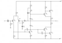
i've looked on the schematic and i think theres no reason that the circuit wout work (i didnt check the resistors/caps values thow).
i found only one problem :
u chouse tip2955/tip3055 output transistors , the rated Vceo is 60V , that means that your psu's rail voltage should be less then 30 - worst case , most amps got higher rail voltages , it might work on the simulation but in real life if your psu voltage is higher then +-30V the amp is dead
Hi Marvellous
On the whole books in SA are very expensive. However, kalahari is not too bad. I picked up Doug Self's latest for about R350, which is pretty good. In fact I have found that Kalahari is normally a cheaper source for CD's as well.
Heres the link:
http://www.kalahari.net
PS: If you register they will e-mail specials to you such as their current 20% off DVD and video sale and send you the occasional R50 gift voucher?
Cheers,
Stuart
With +/- 35V supply rails (and good transistors) the amp will be able to deliver 150W RMS into 4 ohms; and 75W RMS into 8 ohm.
Best regards,
hb
Best regards,
hb
UpDate!
tHANKS Every body😎
sss Thanx for pointing that out!
I confused VCBO (100) with VCEO(60)
sajti Thanx I have changed outputs to Tip35c & 36c
thanks Stuart for the link will go & see
hugobross how did you calculate the output power?
I have updated the schemetic Any Faults?
What is the maximum Voltage this amp can take?
Attachments
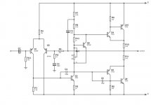
The CFP in the output stage is extremely difficult to handle. Probably you get in trouble with your DC bias. I would not use a BC549/550. And maybe your output stage will oscillate (so as many others and my also at the beginning) Search the tread. It's easier to use a (triple) darlington stage as output. Much easier!
Marvellous,
be careful with the output devices only the "B", or "C" version is OK. The B can handle 80V, the "C" can handle 100V.
If You can get MJ15022/23/24/25, or MJ15003/4, they are also fine for this application.
I agree with bocka, to change the bias regulator from BC549, to BD139, and put this transistor to the heatsink to avoid thermal runaway.
But I think there will be no problem with the DC bias, and I think it's not difficult to use.
Sajti
If you're mounting the BD139/140 together with the Vbe multiplier and the output devices to a large heatsink, you get only a weak coupling of the junction temperature back to the Vbe multiplier stage. This comes from the high BD139 thermal resistance to case. If you are using an infinite heatsink (and a large heatsink is nearly infinite to the SOT126 devices) there is no information (no feed back path) about the actual temperature of the driver. And the output current is very dependant from the Vbe of the driver. Large emitter resistors on the output bjts will help.
sajti said:Marvellous,
be careful with the output devices only the "B", or "C" version is OK. The B can handle 80V, the "C" can handle 100V.
If You can get MJ15022/23/24/25, or MJ15003/4, they are also fine for this application.
Sajti
agreed ,the same with tip35/36 !!!!!!
mj15003/4 and mj15022./.23.. are high power transistors ,dont put them instead of tip31/32 ,those can (and should be!!) be lower power transistors!!!!
i'll reccomend u to use mj15003/4 as output transistors (instead of tip35/36)
Let's discuss about thermal compensation:
1, The thermal resistance of "juction to case", and "case to sink" is no problem in this case. Remember this is problem if Your trannies dissipate power. The bias sensor device doesn't dissipate high power. So the junction will be almost same temperature as the heatsink.
2, With CFB, the thermal runaway caused by the driver but not the output device. This is true, because the feedback loop avoid the change of output device's temperature change.
Sajti
Marvellous said:So if I change BC549, to BD139 and Increase the output resistors to 0.1 The Amp shuold be fine?
The emitter resistors (R10, R11) is OK with 0R33.
Sajti
CFP bias
I have an amp with CFP output stage. There's absolutley no problem to get stable bias. No problems at all. I mounted the the Vbe multiplier transistor on top of the driver transistor. Reffering to the schematic above: Q8 mounted on top of Q4. I also used the same sort of transistor for Q8 and Q4.
The CFP in the output stage is extremely difficult to handle. Probably you get in trouble with your DC bias
I have an amp with CFP output stage. There's absolutley no problem to get stable bias. No problems at all. I mounted the the Vbe multiplier transistor on top of the driver transistor. Reffering to the schematic above: Q8 mounted on top of Q4. I also used the same sort of transistor for Q8 and Q4.
Follow Up
So Changes that I must Make are
1. Leave the Emitter resistors (R10, R11) as 0R33.
2. Change BC549, to BD139
3. mount Q8 on top of Q4
What is the maximum Voltage that this Amp can Handle?
So Changes that I must Make are
1. Leave the Emitter resistors (R10, R11) as 0R33.
2. Change BC549, to BD139
3. mount Q8 on top of Q4
What is the maximum Voltage that this Amp can Handle?

The maximum voltage depended by the transistors You use.
With this devices the maximum voltage about +/-40V, but as I know T3 is the limit for the voltage. Maybe it can be change to MJE340.
But there is another limitation:
Higher voltage means higher output current. And the output device has some limitation to handle the higher current. So over 35V I recommend to use more output devices parallel.
Sajti
that makes sense to me!
but now
if I Parallel my outputs then can the output stage handle more voltage or will it be able to handle more current
but now
if I Parallel my outputs then can the output stage handle more voltage or will it be able to handle more current
- Status
- Not open for further replies.
- Home
- Amplifiers
- Solid State
- Help on SoundBoy Amp