And You can reduce the R1 to 0.1ohm. Due the local feedback inside the CFB the value of this resistor is not really critical.
I found that some small resistors (say 1-2ohms) series with the base of the output trannies help to avoid oscillation.
Sajti
I found that some small resistors (say 1-2ohms) series with the base of the output trannies help to avoid oscillation.
Sajti
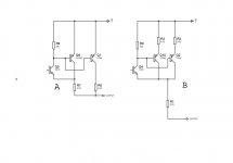
R3 en R12 must be the same value! (the whole schematic)
it's quite easy:
Uv = supply (rail) voltage
Zl = load impedance (4 ohm, 8 ohm, ...)
Prms = continuous power
Prms = (Uv x Uv) / (Zl x 2)
actually Prms will be a little smaller, because there will always be a Uce across the transistors
best regards,
HB.
hugobross how did you calculate the output power?
it's quite easy:
Uv = supply (rail) voltage
Zl = load impedance (4 ohm, 8 ohm, ...)
Prms = continuous power
Prms = (Uv x Uv) / (Zl x 2)
actually Prms will be a little smaller, because there will always be a Uce across the transistors
best regards,
HB.
R3 en R12 must be the same value! (the whole schematic)
hugobross So you mean they must be both 22K
or must they be both 27K

with 27k the gain is 27x and with 22K it's 22x, but the most important thing is that both resistors have the same value (otherwise the LTP is not balanced well). gain = R3/R2
You can also place resistors of 47ohm (more or less) in series with the emitters of Q1 and Q2 to reduce small differences between both transistors.
best regards,
HB
You can also place resistors of 47ohm (more or less) in series with the emitters of Q1 and Q2 to reduce small differences between both transistors.
best regards,
HB
- Status
- Not open for further replies.
- Home
- Amplifiers
- Solid State
- Help on SoundBoy Amp