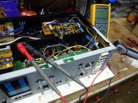
I'm trying to solve a problem on power amp board of a Sansui AU-D5 after I did a full recap. The protector circuit does not allow the signal to the speakers. When I measure the voltage on terminal 95 and 100 in the attached drawing, with volume knob on minimum, I get -31 volts? Further on I measure almost the same negative voltages close to 30volts at the base of transistors Q11-15....
I'm not too experienced on this area and wonder if someone can tell me what could cause this unbalance? Thanks in advance.
I'm not too experienced on this area and wonder if someone can tell me what could cause this unbalance? Thanks in advance.
Attachments
Faulty Technician....
In future, do the job in stages.....replace couple of caps, test....replace a couple of caps, test....etc until done. That way less unwelcome surprises !.
Also wire a 40W or 60W lamp in series with the mains supply to limit fault currents and component blow ups while you are fault finding.
Ok, terminals 95 and 100 are your amplifier stage outputs, and should be close to 0v, as you probably know.
Both channels are exhibiting the same fault so check power supplies...positive supply on terminal 92 and neg supply on terminal 97.
Also check for pos and neg supplies on kR41 and kR42 respectively, and check that terminal 91 is at ground.
Check your work thoroughly....look for broken tracks next to the caps that you have changed, and look for short circuits (solder bridges) too.
Good luck, Dan.
Thanks for your help Dan. Both 92 and 97 have +48 and -53V Volts and 87 and at kr 41/42 resp +48 and -48 volt as per manual. I just measured at terminal 91 and found a steady -500mv. This should be close to zero with the volume at zero right? I disconnected the power supply on the tone control amp to zero the voltage at 91 and now the speaker outputs are around 0.35 volt 🙂. So the problem must be coming from the tone control board putting a steady -500mv on the input... I'll have to check this board 😀
To limit the current, do I put a lamp in serie on the ac or on the dc side of the main transformer?
To limit the current, do I put a lamp in serie on the ac or on the dc side of the main transformer?
Step By Step....
Ok, +48V and -53V is of concern....the main power rails to the output stages should be balanced (equal).
Reasons could be a dry psu cap (12,000uF 63V) on the pos side....check those measurements and ensure that you are referencing to the midpoint of the two main caps.
If still same DC readings, switch your multimeter to AC and check for differing ripple on B+ and B- rails at the caps.....this will reveal a dud cap.
Short 88 to 89, and 91 to 89 (ground both amp inputs) and check DC conditions of both power amp stages and check if the power amps are ok.
Do this and report back.
Dan.
The 60W lamp connects across the mains input fuse holder (remove the fuse) and the lamp should glow dull yellow/orange.To limit the current, do I put a lamp in series on the ac or on the dc side of the main transformer?
Ok, +48V and -53V is of concern....the main power rails to the output stages should be balanced (equal).
Reasons could be a dry psu cap (12,000uF 63V) on the pos side....check those measurements and ensure that you are referencing to the midpoint of the two main caps.
If still same DC readings, switch your multimeter to AC and check for differing ripple on B+ and B- rails at the caps.....this will reveal a dud cap.
Short 88 to 89, and 91 to 89 (ground both amp inputs) and check DC conditions of both power amp stages and check if the power amps are ok.
Do this and report back.
Dan.
Thanks on the info about the lamp Dan. Sorry, both 92 and 97 have +53 (not 48). This is ok as per manual. I found the issue in the control boards F3232/33 where a wire from the volumeknob made contact with another terminal causing a neg.voltage on the amp board input . All is fine now. I just adjusted the DC 0volt on both channels and no problem with setting the bias at 15mv.
So, all well Dan. Thanks so much for your time and help looking into this. I was getting nuts of this thing.
So, all well Dan. Thanks so much for your time and help looking into this. I was getting nuts of this thing.
Attachments
- Status
- Not open for further replies.