Alright solder in Pin 3 and 4 on IC-1 pulled out both C1 and C2 out of the board. Relay still is stuck in protection mode and I have 4.44v on pin 3 and 5.2v on pin 4. Thanks
And are you seeing a still higher offset voltage on the main amplifier output as measured on the 0.47 ohm emitter resistors ? This is where we determine if it is a problem with the protection or a problem with the main amp.
Mooly I am seeing 42.9 v at both TP 31 and TP 33, If I am reading that schematic correctly that is the junction of R47 R49 are the Test points as well as R 48 & R 50. So basically I'm seeing the 44.3 volts at pin 1 on IC-1. When I measure across each resistor R 47 thru 50 I am not getting any voltage, I know I was getting some MV across there before if I remember right. I also have continuity across each of those resistors, not sure if I should have it? Also don't know if this has any bearing on the situation but I'm reading voltages on all the TO-3P transistor Q 19, 21 &20 22 ECB at Emitter is 43v Collectors -/+44v and base 43v its the same reading across all 4 transistors.
So you have a massive DC offset at the power amp outputs which I don't think you had earlier. The offsets were low and the bias was OK before.
So again you have weird problems on both channels which is unusual.
I think you are really working outside your comfort zone with this 🙂 and with you having replaced caps and transistors (which you mention in post #1) there is just so much possibility of errors and problems with non genuine parts that this really needs a skilled technician sat in front of the amp to see what is really going on.
What do you think ?
Basically the only parts that aren't orginal at this point in time in the amp are the TO-3P transistors and the caps. The only cap that aren't of same value is the power supply caps, which I went from 7500 to 8200uf and only because they don't make the 7500uf. I could put the original TO-3P back in Mooly. However there was the problem from the start with this Amp, which is why I did the recap. However to be honest with you and I know you can't tell a good capacitor from a bad one by looking at it, with that being said the old one really had no bulges or stuff leaking out of them they actually looked pretty dang good. I'd kinda like to keep working on it, I have alot of vested time into it, would like to be able to conqueor it. I understand if you don't want to help me anymore as it has been a time sink for you. I appreciate your time and trouble mooly you have been amazing for not being able to actually see what is going on with. I think I'll keep tinkering on it. I know it maybe out of my comfort zone but hey I'll keep studing the schematics and reading what information I can find til I solve this enigma or blow then dang thing up. Thanks so much for all your help Mooly
I don't mind helping out at all on here, as long as you are realistic about what is possible in trying to diagnose faults at a distance.
Careful voltage measurements starting on just one channel are key to this. Yu could really do with understanding basic semiconductor theory as well so that you could see what is happening and why.
Careful voltage measurements starting on just one channel are key to this. Yu could really do with understanding basic semiconductor theory as well so that you could see what is happening and why.
Thanks Mooly. So I don't feel good about HA12002 IC-1 on amp board, so I ordered a replacement part # NTE1635. I also feel that there is something wrong with NJM4558 even as we had way better offset and bias readings with the NE5532 in there than with the original dual amp ic. I feel after those two are replaced we can the trace any offset voltages better or even see if maybe the culprit isn't the IC-1 anyways. I really do appreciate you, your knowledge is invaluable. I will refresh myself on Semiconductors and theory. Thanks so much Mooly
Okay Mooly put back NE5532 dual amp ic back in the Tone board( I still have C1&2 out of circuit on ampboard). Protection relay switch is still in protection mode so I Checked back across R47&49 had 8.5mv and 8.3mv respectively, I also check across R48&50 had 17.1mv and 17.5mv which looks good. I rechecked IC-1 Pin 1 had 42.4v, Pin 2 had 0v, Pin 3 had 3.75v, Pin 4 had 0v, Pin 5 -4.2v, Pin 6 0v, Pin 7 had 5.4v, Pin 8 0v. Which leads me to believe that something is wrong with HA12002. Once I get the replacement part in I will put it into circuit and let you kwow where we stand. Thank you Mooly
But what about the 40 or more volts you measured the other at TP31 and TP33. Those test points are directly on the amplifier output and so that shows a massive DC fault in the power amps.
Think about the amp as blocks. You have the preamp sections, you have the power amp and you have the protection circuit.
The protection circuit may or may not have a problem at the end of the day. One set of measurements showed you had no DC offset at the power amps, and a day or two later we have 40 volts. So its difficult to say for sure based on those results.
Isolating parts and sections is a good way to prove things but the problem here is that you seem to be having problems in more than one section.
If you isolate these two resistors then I can guarantee that the relay should operate normally providing there is no further issue around the chip. If it does operate consistently and normally then the chip is going to be OK.
Attachments
Okay Mooly I agree I believe we have problems in more than one section of this amp! I will isolate those 2 resistors and let you know what is goin on with IC-1 whether it comes out of protection mode or not. I will take some more indepth readings and post them. I did take some time today to do some studing on semiconductors theory and how transistor worked, diodes worked thanks for the suggestion it was actually pretty cool to watch and reminded me how much i had forgotten so I'll be watching a few more in the series to help me out. I think what ever went wrong with this amp though had a cascading affect on the whole amp. Hopefully, we can isolate the problem into section. I sure hope that it didn't kill some of the transistors as some of them I couldnt even find replacement for as I did some research just in case I needed to replace any of them. Thanks again Mooly time for me to hit the bed I will check in with you tomorrow LOL!
Alright Mooly I isolated both R-57 & 58, HA12002 didn't come out of protection mode. So I will replace it when my new replacement comes in! I also checked the volages across Q 19, 20, 21, & 22. Good news Mooly I am seeing +/-43v on all 4 collectors. I am seeing 0V at the junctions of all the emitters (R47, 48, 49, &50), and I am seeing 5.9 to 6v at all the bases. Once I put in the new IC-1 chip will see what happens, if it doesn't go into protection mode we may be in the clear. Quick question for you. I was looking over the scematic and seeing how the input signal went thru the MIC circuit so I decided to pull that Pot and check it out. When I desoldered it out of the board, the bottom of it had clears signs of Electrolysis on the casing combined with green crystals. I took it apart and found the same thing on the inside of it. I went ahead and cleaned the contacts took off the green crystals on it, and applied a little DeOxit on it. Have you ever heard of this before? If so what do you think could of caused it?
Thanks again
Thanks again
-/+ 43 volts on the collectors is correct.
0V on R47 etc is correct but you said earlier:
and these test points connect to R47 etc.
Do you see 🙂 Every time it is different.
Seeing 6 volts on all the bases isn't right *. The base can never be more than around 700mv away from the emitter voltage for a forward biased (correctly operating) transistor. NPN's will have the base positive with respect to the emitter and the PNP's will have it negative with respect to the emitter.
* one possible exception to that is if the circuit was oscillating as high frequency, something which would render conventional meter readings inaccurate... and so a scope would be used.
The pot problem sounds like moisture (or damp) that has affected things at some point in its history.
0V on R47 etc is correct but you said earlier:
Mooly I am seeing 42.9 v at both TP 31 and TP 33,
and these test points connect to R47 etc.
Do you see 🙂 Every time it is different.
Seeing 6 volts on all the bases isn't right *. The base can never be more than around 700mv away from the emitter voltage for a forward biased (correctly operating) transistor. NPN's will have the base positive with respect to the emitter and the PNP's will have it negative with respect to the emitter.
* one possible exception to that is if the circuit was oscillating as high frequency, something which would render conventional meter readings inaccurate... and so a scope would be used.
The pot problem sounds like moisture (or damp) that has affected things at some point in its history.
My termonology probably isnt the best mooly I apoligize for that. As far as the base voltage I should of said that what I was seeing was .59v to .6v on the bases. Yes, I was so excited to see the correct voltages that the schematic showed, in my excitement I put the decimal in the wrong place but I did check the voltages again and I am seeing the same reading I had yesterday. I have spent last 2 days studing up on Transistor, diode operations, to better understand not only theory but application as well. That way I could try to explain myself better. Trust me if you ask my wife explaining what I am doing is not a strong point with me. Thanks Mooly
Mooly just was informed today after waiting over a week that the company I ordered my NTE1635 replacement for the HA12002 IC chip didn't have any in stock!!! After I have waited all week for it. Anyways apparently they have discontinued making the NTE1635 and not it is just finding it to begin with that has become a problem! As far as I can see there no replacement part for the NTE1635 so now either you have to find surplus on it or the orginal HA12002, what a "PITA" I did find one but after the hassle from the other company I don't have my hopes at the moment! Do you know of a replacement for this? Thanks
I don't know of any replacements for those although I would have thought there must be some still kicking around.
Tbh, I wouldn't worry to much over the chip... get the amp working first.
Tbh, I wouldn't worry to much over the chip... get the amp working first.
Ok Mooly replacement parts are in and voltages all read correctly on the amp board. The amp doesn't go into protection mode. I soldered R 57 & 58 back in circuit. Turned the amp on it speaker relay clicked on, no problems. I soldered in one at time C1 then C2 same results speaker relay clicked on no problems. Checked my voltages at the different pins on EBC voltages Q 19, 20, 21, 22. They all checked out correctly! I checked the voltages on NTE1635 at each pin they were correct. Went ahead hooked up the amp with phono and tuner and speakers. Turned it on and right channel is still dead! However, I noticed that on the left channel I had to turn up the volume control halfway to get any sound. At 5 it was what I would of expected to hear at say 1 on the volume control, however when I turn it 1 more click(4 clicks between each number 1 thru 10) the sound suddenly jumps up to where I expect it would be at 5 and click. I toggled to tone and the treble and bass worked. One other side note here as well, which I also find troubling, the mic input as I increase it the sound on the volume decrease proportionately. I am wrong in assuming that the problem is combination of preamp board and the actual volume control pot. I will take the control pot apart and see if it is damaged on the inside or even have the crystals I found in the mic input pot. Anyways, LOL other than finding some problems with the dual amp chip and the speaker protection chip I have a dead channel! Thanks Mooly
Alright Mooly, things weren't adding up in my mine so I pulled it apart and decided to recheck my work. I had reversed the wires on the input to the amp board needless to say, I changed it back to where it should of been done and I lo and behold dang if I don't have two working channels! However, I still have some problems. First off still the problems with the left channel on very low volume til I turn the volume to 5 and a click then I have good volume. Before that the right channel overpowers the left. They equalize at the 5 and click! Secondly, I can't turn the volume down on the right channel at all! Third, the mic mixing pot controls the output of the volume. In fact I had to turn it to 10 to turn off the volume! Sounds like wiring problems yet I am not seeing any other crossed wires from what the schematic shows on the rest of the wiring? I am noticing as well that someone else was in this amp before me. I actually pulled up some photo's of the inside of this amplifier and Checked them against the photographs of when I originally opened up this amp and see some wiring discrepancies! Any thoughts as to why the mic mixing input would be controlling the volume, why the left channel doesn't respond til I hit 5 and 1click and why the right channel doesn't work at all in controlling the amp?
FYI the bass and treble work great. The amp actually sounds amazing great sound all inputs are working. So I guess we're down to the volume issues and the mic mixer issues!
Thanks Mooly
Thanks Mooly
Alright Mooly, things weren't adding up in my mine so I pulled it apart and decided to recheck my work. I had reversed the wires on the input to the amp board needless to say, I changed it back to where it should of been done and I lo and behold dang if I don't have two working channels! However, I still have some problems. First off still the problems with the left channel on very low volume til I turn the volume to 5 and a click then I have good volume. Before that the right channel overpowers the left. They equalize at the 5 and click! Secondly, I can't turn the volume down on the right channel at all! Third, the mic mixing pot controls the output of the volume. In fact I had to turn it to 10 to turn off the volume! Sounds like wiring problems yet I am not seeing any other crossed wires from what the schematic shows on the rest of the wiring? I am noticing as well that someone else was in this amp before me. I actually pulled up some photo's of the inside of this amplifier and Checked them against the photographs of when I originally opened up this amp and see some wiring discrepancies! Any thoughts as to why the mic mixing input would be controlling the volume, why the left channel doesn't respond til I hit 5 and 1click and why the volume control doesn't work at all in controlling the right channel!
So progress of a kind 🙂
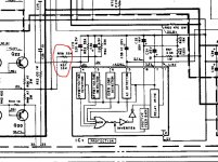
If you follow any of the inputs through the front end and input selector you will see that they do indeed all pass through the mic mixing pot. So that seems normal. You want the pot turned fully to the end that allows the standard audio to pass.
Look at the diagram for that. When the pot is turned fully one way you get mainly the mic signal, as you turn it the other way you get a mix of mic and normal.
From there the signal passes to the volume control control.
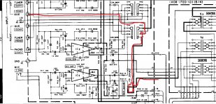
Again look at the full circuit. If you measure from AUX input you should be able to get a direct connection all the way from the socket to the 'top' pin of the volume control.
That is the first thing to check. Make sure the monitor switches are all set correctly to pass the signal.
If you follow any of the inputs through the front end and input selector you will see that they do indeed all pass through the mic mixing pot. So that seems normal. You want the pot turned fully to the end that allows the standard audio to pass.
Look at the diagram for that. When the pot is turned fully one way you get mainly the mic signal, as you turn it the other way you get a mix of mic and normal.
From there the signal passes to the volume control control.
Again look at the full circuit. If you measure from AUX input you should be able to get a direct connection all the way from the socket to the 'top' pin of the volume control.
That is the first thing to check. Make sure the monitor switches are all set correctly to pass the signal.
Attachments
- Status
- Not open for further replies.
- Home
- Amplifiers
- Chip Amps
- Help on a Kenwood KA-405 integrated amp