Dear all,
I need to build a 12 volt 7.5 amp regulated DC power supply for a project.
I have some 2N3055 transistors and 7812 regulators and a transformer with me. I want to use those to make a very simple high current regulated PSU.
The output voltage must not exceed 13.5V or so for the project.
Can I use those to make a power supply like this ?
Can a single 2N3055 handle the load when mounted on heatsink? Or do I need to add some of them in parallel to get more output current?
Kindly give your valuable advice.
Eagerly awaiting your inputs,
Thank you.
Attachments
Last edited:
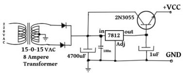
That is simple and will work in principal.
Add a 1u decoupling cap on the emitter of your 3055 and a reversed bias 1n4003 Collector to Base to protect the components against reversed voltages..
If you can keep it cool, it will work but you may need two in parallel with a 0R22 3Watt resistor each to couple their emitters. That will allow for B-E and gain differences in the transistors.
Ohh, Thank you!! 🙂
I'll give them a try for sure and report you back. 🙂
Meanwhile, can I use what I have with me at present? ( I mean those 7812 regulators and 2N3055 and the transformer? ) It can save me some money. 🙂
I am not sure whether my circuit is correct or not.
That is simple and will work in principal.
Add a 1u decoupling cap on the emitter of your 3055 and a reversed bias 1n4003 Collector to Base to protect the components against reversed voltages..
If you can keep it cool, it will work but you may need two in parallel with a 0R22 3Watt resistor each to couple their emitters. That will allow for B-E and gain differences in the transistors.
Thank you really so much!
I have tried to draw the schematic as I understood from your valuable words.
Kindly correct the drawing if I am wrong.
Attachments
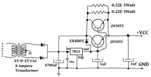
The resistors should be in series with the 2N3055 emitters. Keep in mind that at full current, they will drop some voltage. And, since there's one diode drop from B to E, the output voltage will be about 11.4 volts. One problem with this design is that the output is not truly regulated; there's that diode drop (which varies with current and temperature) and the drop across the resistors (varies with current). You can compensate for the diode drop by putting another diode in series with the Adj pin of the 7812 (pointing down).
The National Semiconductor application notes for three-terminal regulators have a lot of useful ideas. I vaguely remember seeing a high current circuit where the transistor(s) were in parallel with the 78xx, so the regulator could still regulate.
And, consider using the LM723, which is better suited to driving external transistors.
Last edited:
A quasi-discrete regulator like this example is barely more complicated, and doesn't have the drawbacks of 7812+Q's: it truly regulates the output, has a dropout of only 1V and includes a (optional) current protection with an indication.
You can parallel as many 2N3055's as you need, with 0.1 ohm emitter resistors:
You can parallel as many 2N3055's as you need, with 0.1 ohm emitter resistors:
Attachments

Thank you so much.The resistors should be in series with the 2N3055 emitters. ..........You can compensate for the diode drop by putting another diode in series with the Adj pin of the 7812 (pointing down).
I have redrawn the schematic. Kindly check if it is correct or not at your convenience.
The National Semiconductor application notes for three-terminal regulators have a lot of useful ideas. I vaguely remember seeing a high current circuit where the transistor(s) were in parallel with the 78xx, so the regulator could still regulate.
And, consider using the LM723, which is better suited to driving external transistors.
I'll read those. But my technical knowledge is limited but I'll try.
I will try to purchase LM723 if it is available at my place.
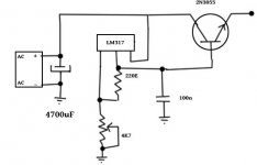
Can I use LM317 instead? I have some unused LM317 regulators in my inventory.
Attachments

Thank you so much! This is a great help!A quasi-discrete regulator like this example is barely more complicated, and doesn't have the drawbacks of 7812+Q's: it truly regulates the output, has a dropout of only 1V and includes a (optional) current protection with an indication.
You can parallel as many 2N3055's as you need, with 0.1 ohm emitter resistors:
But my concern is about the availability of the transistors in my locality.
Can I use an LM317 to further simplify the regulator?
Attachments
The 0R22 resistors go between each emitter and the output. They are in series with each emitter not after both emitters are connected together. The resistors connect the emitters back together.
The 2N3055 is good for 17Amps. You only require 8Amps.
If you keep the heatsink cool, one transistor is sufficient. You then no longer need the 0R22 balancing resistor.
Have a look at this similar design that has over current protection as well. Just choose the power you need and build as many power stages as you need.
This clearly shows the emitter resistors.
High current 12V 30A,25A,20A,15A ham radio power supply | Eleccircuit.com
This clearly shows the emitter resistors.
High current 12V 30A,25A,20A,15A ham radio power supply | Eleccircuit.com
................The 2N3055 is good for 17Amps. You only require 8Amps.
If you keep the heatsink cool, one transistor is sufficient. You then no longer need the 0R22 balancing resistor.
Thank you so much. I can keep the heatsink cool.
Could you kindly re-post the image? For some reason the image is not opening for me.
Ohh great! Very well explained, well documented diy friendly link. I love their approach to build with commonly available components.Have a look at this similar design that has over current protection as well. Just choose the power you need and build as many power stages as you need.
This clearly shows the emitter resistors.
High current 12V 30A,25A,20A,15A ham radio power supply | Eleccircuit.com
Thanks a ton. This is exactly what I needed.
But I have some doubt.
1. If you read the comments in that page, someone pointed out an error in the circuit and some has asked repeatedly whether the circuit is functional or not, but that is unanswered.
2. My only concern is the availability of SCR in my locality.
No, it will not work. There are literally thousands of transistors suitable, the type N°s on the schematic are purely indicative.Thank you so much! This is a great help!
But my concern is about the availability of the transistors in my locality.
Can I use an LM317 to further simplify the regulator?
Not a very sensible advice: the 3055 is rated at 15A, but nobody in his right mind would attempt to use it beyond 5A in a ballast role, where the SOAR plays an important role.The 2N3055 is good for 17Amps. You only require 8Amps.
If you keep the heatsink cool, one transistor is sufficient. You then no longer need the 0R22 balancing resistor.
This circuit has almost the same drawbacks and problems as the original, except they are doubled. Not a very wise choice.
I am confused.
Dear all,
I am confused seeing the difference of opinion among the audio gurus.
I don't have much technical knowledge to determine which way to go even for this simplest circuit.
If you could all unanimously give a verdict like this should be the right approach to do it, that would have been much convenient for me.
I guess I should more specifically tell all of you about my requirement.
I am making a 10 band audio spectrum analyser with 400 LED or more with at least 40 LEDs per band .
I just measured the first vu meter band comprising 40 LEDs.
and here is the result.
1. quiescent current = 09.9 mA ( All LEDs off)
2. normal average consumption per band = 140.59 mA @ 7.69 volt approx. ( I'm using very high brightness LED so I've used higher values for resistors in series with the LEDs to reduce the amount of current.)
3. I found the circuit works well from 5V to 14+ V but I want to keep it under 10 now as I've just seen the performance which is very satisfactory for me.
I need to make 9 more sets like this.
4. At present, for testing, I am using the dual regulated power supply that I had built following the circuit of construyasuvideorockola.com
http://construyasuvideorockola.com/downloads/fuente_v_r_s.pdf
which has been working impeccably with my prototype and any other audio projects. I am using a single supply of course, for this spectrum analyser project.
This circuit uses LM317 and TIP3055 and it survived output short circuit several times earlier.
Hence my questions are:
1. Can I use 2 or 3 pieces 2N3055 in parallel to increase the current flow in place of TIP3055 following the circuit?
2. Alternatively, can I use a computer SMPS to power up this project? Will that be more efficient?
Awaiting your kind reply,
Thank you all.
Attachments

I am not an audio guru. Anyway, for this application, no accuracy is required, and the main drawback of cascading a 7812 with 2N3055s will be the poor efficiency.
It will require the input waveform not to go below ~14V, which should be achievable with a suitably sized transformer of ~14V, and a normal filtering (20,000µF for example).
Three, or at the very least two 2N3055 should be paralleled for this current.
It will require the input waveform not to go below ~14V, which should be achievable with a suitably sized transformer of ~14V, and a normal filtering (20,000µF for example).
Three, or at the very least two 2N3055 should be paralleled for this current.
- Status
- Not open for further replies.
- Home
- Amplifiers
- Power Supplies
- Help needed with a basic 12 volt high current regulator