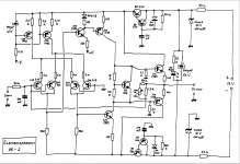
Regarding resistors on input the circuit diagram in my first post showed a fixed 10 Ohm input resistor. I believe this diagram is from the first version of the MC-2, which had dip switches adjustable through a hole in the bottom plate for the the feedback resistor R2. This R2 could be adjusted between 133,1 and 378,3 Ohm.
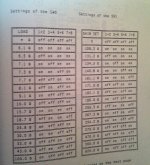
For the later versions R1 and R2 became adjustable and recommendations were as shown in the manual for the preamplifier with a MC module. Actually - this MC module is exactly the same pcb, which is inside the MC-2. Again we see that R1 is minimum 10 Ohm.
So - the original suggestion was for R1=10 Ohm as Marcel notes.
Hans: If R1= resistance in a very short length of wire, as you suggest, how will this effect gain and what value would you recommend using in R2? Pure maths will show gain being extremely high as R1 approaches zero but in practical terms this cannot be the case....
The cartridge resistance is in series with R1 (at audio frequencies anyway), so when R1 = 0, the resistance of the series connection is determined completely by the cartridge.
Your Cart becomes R1.Hans: If R1= resistance in a very short length of wire, as you suggest, how will this effect gain and what value would you recommend using in R2? Pure maths will show gain being extremely high as R1 approaches zero but in practical terms this cannot be the case....
Depending on the gain you are looking for, choose a value for R2.
Suppose your Cart has an Rcart=47R, then gain becomes R2/47, simple as that.
With the additional 47R you have inserted at this moment, gain will be R2/(Rcart+47R) = R2/(47+47) which is 6dB less as without the additional 47R and with 3dB more noise.
There is no benefit at all to insert an additional resistor.
Hans
Assuming it remains stable without one. Chances are that it will remain stable and work just fine, but I still think SMABB should check rather than assume that.
With all respect Marcel, but MC Carts seem to be new territory for you.
I suggest you read a number of test on virtual gnd MC Pre amps or threads in this Forum.
Never has any of the problems occured that you sketch, no oscillation and a perfectly stable Rs in series with Ls.
Whithout these premises it would have been a dead horse.
The only issue that remains is: what topology produces the best sound ?
According to tests it seems that Carts having an Rs above 100R prefer a non inverting input terminated with 10xRs whereas low Rs carts produce their best sounds with virtual input preamps.
Because taking two different amps with the two different topologies to compare things is comparing apples to pears, I have built a switchable preamp so exactly the same amp is used for this purpose.
And based upon my experience with my 38R cart, I can only confirm that my Cart sounds best when driving a virtual input, all documented on this Forum.
Hans
I did exactly the same experiment as Hans did by using a MC preamp that could be wired as current input or voltage input and current input always sounded superior with all MC carts I used (range was from AT F7 with 10 Ohm Ri up to 40 Ohms from a DL 103).
I could not observe any stability issues.
By the way, the MC2 schematic shown in post #1 already has a 100 nF capacitor directly from the negative input terminal to ground. Therefore omitting the 10 Ohm series resistor and directly connecting the phono cable to the negative input makes no difference at all (except for gain and noise) - the few pF cable capacitance in parallel to a 100 nF cap is nothing.
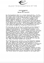
Attached you will find the manual for the original version of MC-2 (the one with dip switches for variable setting of R2).
Is it pure nonsense with all this talk about the circuit being divided into two parts: A "current-sensing" device and a user-adjustable feedback loop? I mean the second part is more or less obvious by now but what do you think about this current sensing device?
Could it be that this current sensing circuitry needs an additional load hence the minimum 10 Ohm in the original version? This 10 Ohm value for R1 has been carried over to the upgraded version as described in manual for the preamplifier.
Just for your reference I have also attached a picture of the MC module when build into the preamp. The pc board is in the upper right corner as a separate board.
Attachments
In my view, that is a lot of marketing blabla to explain that the amp is current input and not voltage input. Even people with some engineering background sometimes have dificulties to understand current drive - the world is mostly voltage centric.
Also the 'self-adjusting' feature is simply the fact that carts with low internal resistance will produce more gain than higher internal resistance carts.
Also the 'self-adjusting' feature is simply the fact that carts with low internal resistance will produce more gain than higher internal resistance carts.
With all respect Marcel, but MC Carts seem to be new territory for you.
True, but I can assure you I have more than enough experience with making all sorts of amplifiers oscillate.
By the way, the MC2 schematic shown in post #1 already has a 100 nF capacitor directly from the negative input terminal to ground. Therefore omitting the 10 Ohm series resistor and directly connecting the phono cable to the negative input makes no difference at all (except for gain and noise) - the few pF cable capacitance in parallel to a 100 nF cap is nothing.
Good point. That should indeed make it quite insensitive to the cable, even without R1, so the potential stability problem is almost certainly a non-issue for this specific design. Great!
Today I found the time to do an experiment as suggested by Hans Polak.
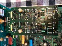
I replaced the 47 Ohm resistors with silver wire (Duelund 0,4 mm silver core wire, cotton in oil) and replaced the 620 Ohm with 332 Ohm to get the same approx. gain.
Hans has a strong point..... the soundstage became really huge, airy and with a lightness to it all, like flowing in the room in front of me. Dynamics improved considerably too. It is quite different from the former setup; I will have to examine a few more days to see if tonal balance is correct. Could take some time to get familiar with these major changes.
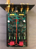
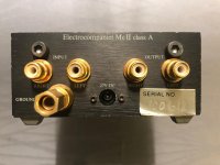
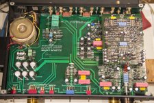
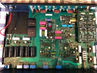
I have attached pictures of the unit as you all have not seen it yet.
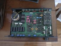
First picture shows the rear. Please note that it says 27 V over the DC power connector. Can this be correct? The diagram for the old/first version says 24 V and I have found specifications also stating 24 V. If correct, will the higher voltage not be converted to heat, as the voltage divider reduces the voltage to 20,8 V ?? The resistors and zener diodes (see attached diagram) will only get hotter, right?
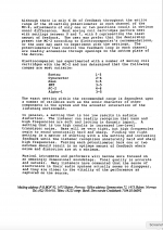
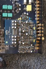
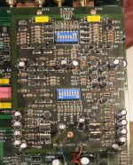
Next up is the circuit and pcb. I have marked the placement of the two resistor sets. The upper set is here made of bare silver wire.
My very good friend is working on Hans Polaks second suggestion: Creating a power supply from batteries. It will be either two battery packs made up of smaller rechargeable batteries or to large 12 V batteries (although not those larger ones made for cars 😀). Update will follow on this subject whenever they are ready for test.
I replaced the 47 Ohm resistors with silver wire (Duelund 0,4 mm silver core wire, cotton in oil) and replaced the 620 Ohm with 332 Ohm to get the same approx. gain.
Hans has a strong point..... the soundstage became really huge, airy and with a lightness to it all, like flowing in the room in front of me. Dynamics improved considerably too. It is quite different from the former setup; I will have to examine a few more days to see if tonal balance is correct. Could take some time to get familiar with these major changes.
I have attached pictures of the unit as you all have not seen it yet.
First picture shows the rear. Please note that it says 27 V over the DC power connector. Can this be correct? The diagram for the old/first version says 24 V and I have found specifications also stating 24 V. If correct, will the higher voltage not be converted to heat, as the voltage divider reduces the voltage to 20,8 V ?? The resistors and zener diodes (see attached diagram) will only get hotter, right?
Next up is the circuit and pcb. I have marked the placement of the two resistor sets. The upper set is here made of bare silver wire.
My very good friend is working on Hans Polaks second suggestion: Creating a power supply from batteries. It will be either two battery packs made up of smaller rechargeable batteries or to large 12 V batteries (although not those larger ones made for cars 😀). Update will follow on this subject whenever they are ready for test.
Attachments
Are the 33 ohm resistors in the supplies really 33 ohm and what's the physical size of the Zeners?
Hi Smabb,
Glad to hear that you succesfully tried the connection without the 47R.
1.3Ah 12V lead acid batteries are very affordable for under €10,- each.
They are probably the best option for this test.
Hans
Glad to hear that you succesfully tried the connection without the 47R.
1.3Ah 12V lead acid batteries are very affordable for under €10,- each.
They are probably the best option for this test.
Hans
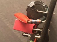
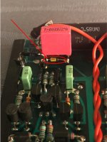
Marcel: The resistors are 33 Ohm on incoming power. Attached picture show one resistor with two orange bands, followed by a black, gold and brown. That should make it a 33 Ohm resistor with 1 % tolerance. It evens measures correctly within that tolerance 😉
The zener diodes are quite small (attached picture) and measures L=2,5 mm, diameter Ø=1,5 mm.
The zener diodes are quite small (attached picture) and measures L=2,5 mm, diameter Ø=1,5 mm.
Attachments
27 V - 10 V - 10 V = 7 V
7 V/(2 * 33 ohm) = 0.1060606... A
Rough estimate for the current that the amplifier needs: 20 mA
Estimated current through the Zeners: 80.606060... mA
Zener dissipation: 806.060606... mW
Allowable Zener dissipation: about 400 mW or 500 mW
I wouldn't dare to put 27 V on it, unless the Zener voltage has been increased to more than 10 V.
Hi all, first post here 🙂. Interesting thread, and I can't contribute much on the theoretical side, I am here to learn and lurk mostly. My technical insights are very limited, and even terminology can be difficult.
But I do own some versions of the EC MC phono stage. I wasn't aware there was an EC MC2 standalone stage, so I have the EC-1 preamp in two versions.
The first is early version 1987, with switchable MM/MC mode. The MC stage uses replacable resistors for load and gain, like the ECMC2. It also has options for using several resistors in combination to get just theperfect match. This is special, and beyond me.
The second (I call it EC-1b) is dated July 1989, and is MC only; that is, they have removed the switch for MM/MC. The MC card can be lifted out, and the signal paths in the multipin connector shorted (sorry for term), and it becomes a MM stage only, 22pf/47kohm with 32db amplification.
This system is repeated in the EC-3 preamp, which also came with a balanced MC stage, basically built on the EC-1 (according to EC). I've attached a pic of this version too, but unfortunately I don't have this MC stage version.
But the EC-1b MC I have is very pleasing to my ears, and made my previous Pro-ject phono box DS obsolete in minutes.
I have only tested the MM/MC version in MM mode, due to lack of resistors. And, I've only tested the MC-version in MC mode, since de-soldering is necessary to remove the MC card.
But both plug into a MM stage, so I presume the MC card could be extracted and used as external head amp?
Also you can see some mods have been done, and neither are in original state anymore.
They are both new to me, few of weeks only, so limited time spent with them. I can say the MM stage works best with higher output carts, and 22 pf is for me a good starting point in a MM stage.
The newer, MC only, is perhaps the star, and I'm currently trying to decide if 15,7 or 18,7ohm sounds best with ATOC9/III, which has DC impedance of 14 ohm 🙂. Gain is more than sufficient.
So, I run both via Tape out, and pre is left in standby mode.
But, from what I understand, I could extract the MC card in my oldest version and make a standalone headamp? Battery powered even?
Of course I'm wondering if it could be made balanced in the process, like the EC3-MC, but I'm afraid the answer would be too difficult for me to implement...🙄.
Regards,
Dagfinn
Attachments

 This is technically a phono stage and would be appropriate in analog source so I will move it there.
Most zeners are operating happilly at 10mA, I put them at 5-10mA. 20+mA is ridiculous.Rough estimate for the current that the amplifier needs: 20 mA.
thread found after moderator measure - ok
Last edited:
The Zeners are used as shunt regulators rather than voltage references, hence they work at a higher current - but with 27 V at the supply input they work at a too high current (about 80 mA while they can handle 40 mA). Assuming they are still 10 V each, that is.
Great new input Dagfinn 🙂
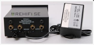
Your contribution also adds new info to this thread, were we are trying to demystify the MC-2. For your info I have attached a picture of the MC-2 with its external PS.
Would it be possible for you to take a clearer/sharper picture of the resistor values scheme from, what I assume is, the manual for the EC-1?
There are more cues to listen for in adjusting both R1 (load) and R2 (Gain) even though Hans Polak has demonstrated, that the R1 contribution is of less importance, or irrelevance as I am sure Hans would express it..
Thanks again Marcel for knowledgeable input on whether 24 V or 27 V was feasible in the power supply. From your calculations we must assume, that there was an error in the screen printing (see attached photo) for this batch of MC-2´s 😀
Attachments

- Home
- Source & Line
- Analogue Source
- Help needed understanding this prepreamplifier