I would like some input on this.
I am repairing a build of this amp where it is humming badly as the regulator transistor is blown. The particular device is hard to obtain so I tried something similar npn of 120v rating and it worked for a while but then blew as well, I imagine due to over voltage as the B+ is 350v in operation and about 400v at switch on.
The build had worked ok for six months or so but I wonder if the design is a bit vulnerable and could be improved.
Are there any similar amp designs I should consider for inspiration on improving this?
Many thanks
The 2SD1409 is listed as a Darlington type so its not just a normal NPN device.
Couldn't we use a high voltage N channel power FET here instead? I think you would need a Zener across Gate/Source for protection but other than its basically the same configuration.
These are lower voltage versions but the topology would be similar.
https://www.diyaudio.com/community/threads/jumas-easy-peasy-capacitance-multiplier.297921/

The transistor or FET needs to be rated to allow the full B+ across it at startup (before the tubes heat up). I would use at least a 600V device to be safe.
Here is one circuit I am using:

Here is one circuit I am using:
And 600 (and 650) volt devices are available in full molded package, with insulation rated for the full voltage.
In case you touch something, and don’t have to jack with insulating the tab.
Call me paranoid but I also put a UF4007 from gate to drain. As well as about a 1mA minimum load on it before the tubes start conducting, and discharge any bypass caps. A 0.1 uF film cap will hold a charge quite nicely.
In case you touch something, and don’t have to jack with insulating the tab.
Call me paranoid but I also put a UF4007 from gate to drain. As well as about a 1mA minimum load on it before the tubes start conducting, and discharge any bypass caps. A 0.1 uF film cap will hold a charge quite nicely.
An improvement would be to remove the transistor, replace it with a reasonable sized choke / capacitor stage and move on.Are there any similar amp designs I should consider for inspiration on improving this?
In a single ended class-A topology, the only variation in supply current is due to the distortion components of the signal and is therefore small. B+ power supply regulation is not required or desired in such a situation. It is just an added complication and failure source. JMHO
Maybe a arrangement like so?:

And use a beefy transistor, I don't think this would have any problems.
And use a beefy transistor, I don't think this would have any problems.
I agree with Suncalc.
I do not think you can call this a "regulated power supply" anyway since it lacks a voltage reference (zener diode or voltage reference tube).
@ romeoleung: I think the stage with the 12AX7 is a form of mu-follower. If so, the anode resistor (68K) of the first section of the 12AX7 is connected correctly in the schematic in post #1.
What seems 'strange' to me is the voltage rating of only 350 V of the capacitor of 100 uF after the bridge rectifier since it seems to see 400 V at start-up.
That supply is not regulated; it is merely buffered by the transistor, which acts as a capacitance multiplier for the cap on its base. Output voltage will slowly vary with line voltage variation, and output voltage variation will be reduced a bit by the transistor due to its low output impedance. In order for regulation to occur, there needs to be some kind of a voltage reference by which a regulator circuit can set a voltage output and maintain it at some value under varying output current conditions. The buffer circuit will nonetheless be better than not having it, but it won't perform as well as a true referenced regulator would.View attachment 1450540
I would like some input on this.
I am repairing a build of this amp where it is humming badly as the regulator transistor is blown. The particular device is hard to obtain so I tried something similar npn of 120v rating and it worked for a while but then blew as well, I imagine due to over voltage as the B+ is 350v in operation and about 400v at switch on.
The build had worked ok for six months or so but I wonder if the design is a bit vulnerable and could be improved.
Are there any similar amp designs I should consider for inspiration on improving this?
Many thanks
Zener or stack of zeners in parallel with C7 and it becomes regulated. Regulated enough for tubes, that is.
Definitely not regulated, it's a capacitance multiplier.
But at least add an RC filter before the collector to reduce the large voltage ripple.
Or an LC filter, but the choke would require more room.
But at least add an RC filter before the collector to reduce the large voltage ripple.
Or an LC filter, but the choke would require more room.
This. Find yourself a new 450V+ rated transistor and add the two protection diodes, and you'll be sorted.Maybe a arrangement like so?:
View attachment 1450627
And use a beefy transistor, I don't think this would have any problems.
Thanks for all the wonderful advice.
Pmillet suggestion is what I am hoping for as it needs to be handful of parts / tagboard compatible.
This is 100v line as it is a Japanese kit from eBay or similar online vendor. It is a neat and tidy build but space is limited for a choke.
Also I actually goofed on the npn device as I mistyped the device name DOH! When looking for an equivalent.
For the brief period that it was working on the npn it sounded nice and humm was not apparent either on scope or audibly though I odd not measure it
An improvement would be to remove the transistor, replace it with a reasonable sized choke / capacitor stage and move on.
In a single ended class-A topology, the only variation in supply current is due to the distortion components of the signal and is therefore small. B+ power supply regulation is not required or desired in such a situation. It is just an added complication and failure source. JMHO
Coughs...bullcookies. SE has the entire signal variability stuck on the power supply. Plus tube nonlinearities. Greater than +/- idle current if turned all the way up... 🙂
Dougals
What was meant was that the change in average DC supply current is due to nonlinearities. When there is zero THD the average supply current will stay constant from quiescent to full signal. When distortion is present the DC supply current will shift.
LOL...average current is quite a different thing from instantaneous current. You have to go PP to get a nearly DC load.
Douglas
Douglas
If the currentwise the entire signal variability would be stuck on the power supply, than where does the current that drives the loudspeaker come from?Coughs...bullcookies. SE has the entire signal variability stuck on the power supply. Plus tube nonlinearities. Greater than +/- idle current if turned all the way up... 🙂
Dougals
I think you overlook the role the output transformer is playing in this (storing and releasing energy with signal).
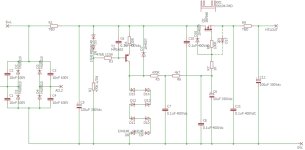
Just to round off this thread (hopefully), I took the recipe kindly suggested by @pmillett and mixed it with the components I had to hand and came up with this result which so far seems very effective and I believe should be stable.
Notes:

Notes:
- The original schem shows a 100uF reservoir cap but in fact it it is a multi section 3x20 in parallel.
- I added a bit more filtration at the front as I was experiementing and it seemed helpful
- I am not sure on the purpose of the suggested load resistor to pull 1mA - enlighten me please @wg_ski
- Home
- Amplifiers
- Tubes / Valves
- Help needed on Regulated power supply on Class A 6L6 amp