Update:
Collected another transformer rated @ 28-0-28, 5A (though my transformer vendor said it is rated @ 10A) Not sure which A is true?
😕
When I told him that I want to return my current 24-0-24, 5A and wand a higher Amp transformer, he said this 24V transformer is also rated at 10A.
😕😕
He didn't stop here and continued adding in my confusions by saying that my rectifier (which was suggested in this thread and I followed that) is wrong and actually making the total volts to 48v.
To get 24V, I should skip the (-) from bridge-rectifier. I should use ground of transformer into the (-) of one 10000uf. If I use (-) from bridge rectifier, then it become 48c supply!!!????
😕😕😕
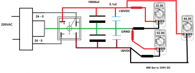
I am following this rectifier where my caps are :
10000uf/63v X 2
35A BR X 1
0.1uf X2 :
![40v-dual-power-supply[1].jpg](https://www.diyaudio.com/community/data/attachments/350/350166-b487e2f4ce15d1edeadaf00e58a94b30.jpg?hash=tIfi9M4V0e "40v-dual-power-supply[1].jpg")

Awaiting experts opinions on these confusions!
Collected another transformer rated @ 28-0-28, 5A (though my transformer vendor said it is rated @ 10A) Not sure which A is true?
😕
When I told him that I want to return my current 24-0-24, 5A and wand a higher Amp transformer, he said this 24V transformer is also rated at 10A.
😕😕
He didn't stop here and continued adding in my confusions by saying that my rectifier (which was suggested in this thread and I followed that) is wrong and actually making the total volts to 48v.
To get 24V, I should skip the (-) from bridge-rectifier. I should use ground of transformer into the (-) of one 10000uf. If I use (-) from bridge rectifier, then it become 48c supply!!!????
😕😕😕
I am following this rectifier where my caps are :
10000uf/63v X 2
35A BR X 1
0.1uf X2 :
Awaiting experts opinions on these confusions!
that Connection is correct. and will give you +/-33VDC with 24-0-24VAC transformer.
where this guy takes 48V total from i don't know.
without the 0 point it would have been a single +66V supply.
where this guy takes 48V total from i don't know.
without the 0 point it would have been a single +66V supply.
Thanks, that clarifies the things. I think he didn't count the rectified volts and he meant its 48V single supply in total when not using ground.that Connection is correct. and will give you +/-33VDC with 24-0-24VAC transformer.
where this guy takes 48V total from i don't know.
without the 0 point it would have been a single +66V supply.
---------------------------------
Anyways, I also got some fuses of 2A & 3A, and fuse boxes today. Which fuses are more suitable fuse for these applications:
24-0-24, 5A or 10A (uncertain about 'A') for 5 X LM3886
28-0-28, 5A or 10A (again uncertain about 'A') for 200W Toshiba sub amp board.
Will make the same PSU for the SUB application also like I made earlier, collected the stuffs for that as well.
There is also a sub crossover which needs 18-0-18, 500mA power supply, I got provision for it in the sub amp transformer. What PSU I need for this crossover? Or can I use this PSU for this complete sub application : http://diyaudiocart.com/Wintek-Dual-Rail-PSU-Module. I already have this readymade PSU with me.
I also have a speaker protection circuit : http://diyaudiocart.com/Wintek-Speaker-Protection-Module
Should I use this SP in the sub amp or not needed?
This is the sub amp board I have : http://diyaudiocart.com/Wintek-200W-Mono-Toshiba-2SA1943-2SC5200
Last edited:
the transformers is at least 550VA together. so you might need a softstart.
fuse size can not be answered until one knows the VA raitings for sure.
regarding the PSU, there is no info on it. so i can not suggest anything.
fuse size can not be answered until one knows the VA raitings for sure.
regarding the PSU, there is no info on it. so i can not suggest anything.
Can't I measure the Amperage with the help of a multimeter? If I can then how to measure?fuse size can not be answered until one knows the VA raitings for sure.

Thanks, that makes my task much easier 😀With following update you can use the PSU you have for your Sub-woofer
Also ordered rest of the LM3886 kits but not able to find suitable heatsinks locally. I want 12 inch longer heatsinks where I want to attach two LM3886 on one heatsink and other two on another similar heatsink. These heatsinks can also act as sidewalls of my cabinet.
Can't I measure the Amperage with the help of a multimeter? If I can then how to measure?
The 5A you have from the vendor is normally per secondary. That is a total of 2x5A = 10A
Hmmm! That looks like what he meant since he also supplies transformers for inverters and I think there they don't use earth/ground hence the 24-0-24 supply is measured as 48V in total hence the same kind of formula is applicable on Amps. So in reality the transformer is just 5A if used in 24-0-24 format.The 5A you have from the vendor is normally per secondary. That is a total of 2x5A = 10A
Should I get a 8-10A to power 5 X LM3886 or 5A is enough to extract some 60W output on 4 ohm speakers?
Make sure that whatever you power up LM3886 amplifiers should not be more than +/-35 volts DC.
Try not to say 8-10A transformers. mention it in VA rating.
100 VA transformer for one Lm3886 is apt. which is equivalent to 24-0-24 /4 amps (in Indian local terminology).
I guess 5.1 channel means -for Movies! Lower Va transformer will make your amp sound very harsh at moderate sound levels.
Try not to say 8-10A transformers. mention it in VA rating.
100 VA transformer for one Lm3886 is apt. which is equivalent to 24-0-24 /4 amps (in Indian local terminology).
I guess 5.1 channel means -for Movies! Lower Va transformer will make your amp sound very harsh at moderate sound levels.
Last edited:
...Should I get a 8-10A to power 5 X LM3886 or 5A is enough to extract some 60W output on 4 ohm speakers?
Since you already have one tranny, buy another one of same spec/make if need arises for a separate tranny for rear/central ch. with the added functionality of "powering off" when not required i.e. stereo mode. Current wise, the rear ch. would be less demanding as compared to front ch.
Last edited:
Well yesterday got my another transformer : 28-0-28, 5A and today tested it. Connected this tranny with a light bulb in series but the light bulb remained glowing. I also tried to check again by connecting my rectifier but again the situation was same. Tried to measure the volts with multimeter but it didn't show anything.
Then I disconnected all the wires and opened joint of center two wires which need to join to make '0' so not there were total 4 wires. Now I connected the tranny into power supply and this time bulb didn't glow even for once. I tried to measure the current in all the four wires, both side wires didn't show anything but when I connected multimeter to both center wires, it shown 18.5V.
So this is the story of 28-0-28, 5A which reached to unhappy end. Will again have to 15kms away in the center of the city though all the traffic to get this tranny checked
----------------------------------
Coming to my 24-0-24, 5A transformer.
Decided to confirm what volts it actually is producing. Connected the rectifier and connected the power supply with light bulb for fail-safe, bulb glown once and turned off, everything was okay. connected multimeter to ground of the tranny and +/- one by one, it was showing some 18.5V. Why not 24??? Then connected ground at the rectifier's end and +/- of the rectifier, it started showing 55-58.5V on positive end but nothing on negative end . Why not around 30???
Can somebody tell me whats going on wrong here?
----------------------------------
BTW connected this 24-0-24 in the same situation with my sub amp board, connected line-in, a damaged speaker and it started played. So my connections on the sub amp were also okay. I turned it off after half a minute since I wasn't sure about the power supplies.
Guys, please help me here.
BTW ordered rest of four LM3886 boards also and they may reach to me by Saturday. Want to complete this project on Sunday so that I can watch a movie. My existing amp has become terribly noisy since I have performed lot of experiments on that so living without music/sound which is not any less then breath for me 😕
Then I disconnected all the wires and opened joint of center two wires which need to join to make '0' so not there were total 4 wires. Now I connected the tranny into power supply and this time bulb didn't glow even for once. I tried to measure the current in all the four wires, both side wires didn't show anything but when I connected multimeter to both center wires, it shown 18.5V.
So this is the story of 28-0-28, 5A which reached to unhappy end. Will again have to 15kms away in the center of the city though all the traffic to get this tranny checked
----------------------------------
Coming to my 24-0-24, 5A transformer.
Decided to confirm what volts it actually is producing. Connected the rectifier and connected the power supply with light bulb for fail-safe, bulb glown once and turned off, everything was okay. connected multimeter to ground of the tranny and +/- one by one, it was showing some 18.5V. Why not 24??? Then connected ground at the rectifier's end and +/- of the rectifier, it started showing 55-58.5V on positive end but nothing on negative end
. Why not around 30???Can somebody tell me whats going on wrong here?
----------------------------------
BTW connected this 24-0-24 in the same situation with my sub amp board, connected line-in, a damaged speaker and it started played. So my connections on the sub amp were also okay. I turned it off after half a minute since I wasn't sure about the power supplies.
Guys, please help me here.
BTW ordered rest of four LM3886 boards also and they may reach to me by Saturday. Want to complete this project on Sunday so that I can watch a movie. My existing amp has become terribly noisy since I have performed lot of experiments on that so living without music/sound which is not any less then breath for me 😕
Last edited:
Well again checked the transformer after removing the bulb in series.
the 24-0-24 transformer showing 24-25 so its true 24-0-24 tranny. But the it showing 72 on positive (yellow wire) of PSU but nothing on negative (black wire). Green wire is zero where I tapped com pin of the MM, please check the pic:
 3
3
is there something wrong with the PSU?
Also checked the 28-0-28 but nothing happening there. When I break both central wires, only they show reading of 25 but other two wires where I should have got 28, are not showing anything. winding part also became too hot and its still too hot. 🙁
the 24-0-24 transformer showing 24-25 so its true 24-0-24 tranny. But the it showing 72 on positive (yellow wire) of PSU but nothing on negative (black wire). Green wire is zero where I tapped com pin of the MM, please check the pic:
3is there something wrong with the PSU?
Also checked the 28-0-28 but nothing happening there. When I break both central wires, only they show reading of 25 but other two wires where I should have got 28, are not showing anything. winding part also became too hot and its still too hot. 🙁
Last edited:
Center tapping of transformer is not connected.. Or you are not selecting proper Center tapping of transformer.. Please contact trans maker to verify center tapping wires.
Please solder all wires.. loss wire may result in improper connections.
SOLDER ALL WIRE JOINTS.
Please solder all wires.. loss wire may result in improper connections.
SOLDER ALL WIRE JOINTS.
Last edited:
When I first connected the transformer, center wires were joined together but when light bulb remained glowing, I checked the volts and no reading was appearing on MM. Later I thought maybe the vendor has messed up the center wires so I disconnected just to check the readings which resulted in reading only on center wires and no reading on rest of the two wires.Center tapping of transformer is not connected.. Or you are not selecting proper Center tapping of transformer.. Please contact trans maker to verify center tapping wires.
Please solder all wires.. loss wire may result in improper connections.
SOLDER ALL WIRE JOINTS.
Will take it back to the vendor.
Anyways how do I make sure my PSU is correct?
I tried to measure the readings by connecting the PSU on my previous 24-0-24 transformer but it was showing some 72v on positive side wire of the PSU and 0 on negative side. Shouldn't it be some 30-32V on both +/- sides? Is there anything wrong with the PSU? Reading on transformer was corect and it was showing 24v on both ends.
How to diagnose and correct the fault?
Last edited:
My reply was in response of 24v transformer only.. are u using a digital or analog meter for reading voltage..
Please find attachment as reference voltage reading layout.
Thanks, I was measuring in same way. I am again checking to verify and I am getting 24 on both sides (black wire of MM on 0 and red wire on either sider ) of the transformer.
But when I connect black wire on '0' of the PSU and red on (+), I get 72v and 0v on (-) side. When I connect black on negative of the PSU and red on positive, I get 144v.
Even when power is switched off and transformer wires are out of the power socket, current is still there on the PSU and I am getting reading of 67 and 134. When I disconnect the PSU from the transformer, still it is giving me same reading, the stored volts aren't draining from the PSU.
I checked multiple times, my connections on the PSU are correct as per the diagram discussed earlier.
I am using digital multimeter.
Last edited:
It's strange you are getting 72 VDC from 24 VAC.
With 72v DC you must have burned your test run of LM3886.. but your test was fine... How come....???????
Is your multimeter giving correct DC reading..
Please share a pic of multimeter showing reading.
AFTER LOOKING AT LAST PICTURE CLOSELY IT SEEM YOU HAVE CONNECTED THE BRIDGE RECTIFIER WRONGLY.
With 72v DC you must have burned your test run of LM3886.. but your test was fine... How come....???????
Is your multimeter giving correct DC reading..
Please share a pic of multimeter showing reading.
AFTER LOOKING AT LAST PICTURE CLOSELY IT SEEM YOU HAVE CONNECTED THE BRIDGE RECTIFIER WRONGLY.
Last edited:
Maybe at the rectifier was working fine at the time of testing and something may have gone kaput after that. Another reason maybe that I continued my test when bulb was still there so volts were on lower side and were not enough to damage the LM3886.It's strange you are getting 72 VDC from 24 VAC.
With 72v DC you must have burned your test run of LM3886.. but your test was fine... How come....???????
Will try to take pics later but I did took readings multiple times and it never showed what was expected.Is your multimeter giving correct DC reading..
Please share a pic of multimeter showing reading.
Here are few more pictures of the rectifier:AFTER LOOKING AT LAST PICTURE CLOSELY IT SEEM YOU HAVE CONNECTED THE BRIDGE RECTIFIER WRONGLY.
The yellow wire going to the 10000uf cap is attached to (+) of the BR


Last edited:
Connections are OK..
May be rectifier have gone faulty when u tested it with your 28-0-28 faulty transformer..
But it should not be giving that high DC voltage..
Test your PSU PCB you purchased earlier with 24-0-24 transformer for DC Voltage reading.
May be rectifier have gone faulty when u tested it with your 28-0-28 faulty transformer..
But it should not be giving that high DC voltage..
Test your PSU PCB you purchased earlier with 24-0-24 transformer for DC Voltage reading.
- Home
- Amplifiers
- Chip Amps
- Help Needed on DIY LM3886 based 5.1 Channel AMP for PC Home Theater