Using a 3886 reliably with a 28-0-28Vac transformer depends very much on the transformer specification and your mains voltage.
A 230:28-0-28 Vac 7% regulation transformer running on 243Vac will give a very different voltage from a 240:28-0-28Vac 4% regulation running on 228Vac !!!!!
You must know your transformer and you must know your variation in the mains supply voltage.
A 230:28-0-28 Vac 7% regulation transformer running on 243Vac will give a very different voltage from a 240:28-0-28Vac 4% regulation running on 228Vac !!!!!
You must know your transformer and you must know your variation in the mains supply voltage.
5A output seems low. Is 2x5 ampere or 5A total.
38 volt is also at bit high. I don't think the amplifier will be happy if you have 4 ohm subwoofer.
read more here
http://chipamp.com/docs/lm3886-manual.pdf
38 volt is also at bit high. I don't think the amplifier will be happy if you have 4 ohm subwoofer.
read more here
http://chipamp.com/docs/lm3886-manual.pdf
Wait, wait, wait.... I think there is a confusion, let me clear a bit.5A output seems low. Is 2x5 ampere or 5A total.
38 volt is also at bit high. I don't think the amplifier will be happy if you have 4 ohm subwoofer.
read more here
http://chipamp.com/docs/lm3886-manual.pdf
My sub amp kit is different : Wintek - 200W Mono (Toshiba 2SA1943 / 2SC5200)
The transformer is 28-0-28, 5A for this kit. Isn't that enough for this 200W kit which will drive my 4ohm sub driver?
I am using LM3886 only for my 5 main channels. where I am going to use 24-0-24, 5A
In total there are two different transformers and I am keeping both the application separate from each other. Sub amp and transformer will go into a separate cabinet and rest of the five LM3886 main channel kits will go into a separate cabinet with a separate transformer.
rakesh_sharma23 may through more light on the transformer choice part. I had a detailed talk over phone with him before deciding on transformers and he cleared lot of my other doubts also. 🙂
Last edited:
Jack,
that link showing 200W into 8r0 cannot be a reliable truth.
1943/5200 cannot give 200W into 8r0. They will blow up when you try to test that level of power output.
that link showing 200W into 8r0 cannot be a reliable truth.
1943/5200 cannot give 200W into 8r0. They will blow up when you try to test that level of power output.
5 channels LM3886 with only 5A. I haven't build gainclones, but to me it seems to be very little power. I know that for normal audio input 1/8 of power is fine, but if you really want's to crank up the volume with moderne heavily compressed music, I think it's not enough.
My sub driver is 160W, 4 ohm rated, and I will be using my setup at home, is my SUB AMP choice and transformer not right for my application? 😕Jack,
that link showing 200W into 8r0 cannot be a reliable truth.
1943/5200 cannot give 200W into 8r0. They will blow up when you try to test that level of power output.
What we calculated was some 50W for 4ohm speakers. And there will be a PSU also to regulate the power.5 channels LM3886 with only 5A. I haven't build gainclones, but to me it seems to be very little power. I know that for normal audio input 1/8 of power is fine, but if you really want's to crank up the volume with moderne heavily compressed music, I think it's not enough.
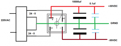
Please have a look at the PSU for LM3886:
Red and blue wires are coming from 24V supplies and black is coming form 0.
35A bridge rectifier : green is from (-) and yellow is from (+)
10000uf, 63V : right side - yellow is connected at (+) and left side green is connected at (-). Black is connected at opposites.

Is that correct?
will the wire from the blue 0.1uf, 100V will go into the amp board?
Where the black wire will go then?
Now can I connect all this to the transformer and power it on?
Red and blue wires are coming from 24V supplies and black is coming form 0.
35A bridge rectifier : green is from (-) and yellow is from (+)
10000uf, 63V : right side - yellow is connected at (+) and left side green is connected at (-). Black is connected at opposites.
Is that correct?
will the wire from the blue 0.1uf, 100V will go into the amp board?
Where the black wire will go then?
Now can I connect all this to the transformer and power it on?
Last edited:
NO NO.. Do it like this.. and use 18GWS wire for power supply. these wire can't handle more than 1 amp of current.
0.1 uf caps should be parallel to 10000uf caps..
PLEASE.....PLEASE Sir, read all basics about power supply and electronics ones more... try to understand why each components is used and more...
If you continue like this than you will end up with a disaster.
0.1 uf caps should be parallel to 10000uf caps..
PLEASE.....PLEASE Sir, read all basics about power supply and electronics ones more... try to understand why each components is used and more...
If you continue like this than you will end up with a disaster.
Attachments
Last edited:
Ive once killed a petty expensive class D amplifie boad...
Got "nice" readings fom the powe supply but you know what...
My cente taps was wired like... I had 48 volts on both sides but 0 between both 48s
What i mean... You transfome has 4 output wires, get multimeter...
Measure resistance to find 2 of the coils, mark the wires...
Now plug the transformer in without nothing on the outputs...
Now connect one of the 24V outputs to the other 24V ouput...
Now measure voltage between both 24V outputs that are alone
You should get eading of 48V or something very close.
If you dont, switch one of the 24V outputs and measure again until you get measurements between both 24-0 as 24V and 48 between both 24V outs.
If you have done that... Go and find serious wires... 1,5mm2 would be good...
Solder one to 0 of the transformer and 2 to the outputs.
Like green 24, 0 black 0 , green 24
The green ones go to your bridge rectifier and 0 remains open till you connect the capacitors.
Now you have connected and soldered everything together. Soldering is one hell of a drug 😀
Post27.
The black wires form a three way PSU Zero Volts.
The picture looks correct electrically.
There are 3 output wires: +ve -ve and Zero Volts.
BUT !!!!!!
your picture shows ENORMOUS radiating LOOPs, that will emit interference and will affect all low level receiver circuits inside the chassis.
You MUST make all the LOOPs small. Very SMALL.
Look at the three wires from transformer to rectifier. Two connect directly to the rectifier AC1 and AC2. The 3rd is the centre tap. This centre tap wire must be twisted with AC1 and AC2 to form a triplet. Leave the centre tap long. Solder AC1 and AC2 to rectifier. Solder +ve and solder -ve to the rectifier. Now using that long centre tap and + & -, form a new triplet. Run this new triplet to the capacitors. Solder + to cap, solder - to cap. solder a wire across the caps zero volts. Solder the 3rd wire of the triplet to that zero volts wire.
Now solder + & - and zero volts to the caps. Form yet another twisted power triplet. Run this triplet to the amplifier.
All the twisted triplets ensure the minimisation of the LOOP areas.
I forgot.
Leave out those fast caps.
They are more likely to introduce a problem, than to cure a problem.
Leave out those fast caps.
They are more likely to introduce a problem, than to cure a problem.
picture is correct to some extant as such he is trying to use 0.1uf in series with supplied voltage.
I don't think 0.1 uf will create any problem... anyways it totally depend on personal preference.
I don't think 0.1 uf will create any problem... anyways it totally depend on personal preference.
Last edited:
adding a low esr cap in parallel to another cap can create instability............... I don't think 0.1 uf will create any problem... anyways it totally depend on personal preference.
Adding a snubber can attenuate ripples/oscillation.
A snubber is a resistor to dissipate the HF energy, NOT a capacitor !
Dear (Capt.) Jack Sparrow, if the amp voltage is 28V, divide it by 1.4. that is the tr ansformer voltage you need. 28/1.4=20V. add 2V for drop in rectifier. LM chips work on dual voltages. so use 22-0-22V trafo. As for power rating, assume a 60% efficiency for the amp. if it deliver 60W. trafo power is 60/0.6=100W orVA. 100/22=4.4A that is the current rating of the trafo.But the specs sheet of LM3886 board saying +/-28v for 4 ohms load.
What is the needed ampere here? When I emailed my amp kit vendor, he recommended 650VA 12 to 13 ampere for 5 X LM3886 and 500-520VA / 9A for 200W Toshiba kit. And you are saying just 300VA. Which one to pick?
My major confusion is what I need to say to the transformer vendor when I go at there so that he can give or prepare me the right transformers for both applications. Also, I would need 18-0-18VDC 500mA tapping for the sub crossover so how to get that? Will there be any provision in the sub transformer?
This is main power supply for the AMPs so a crucial thing and I am worried about it. More I read on the transformers, more I get confused. 😕
First of all I want to buy all the required transformers, will step into next stage after getting all the transformers.
24v Transformer will provide following DC voltage
(24*1.4)-2 = 31.6 ~ 32VDC
And please check on the first page of LM3886 Datasheet it says
"50W Cont. Avg. Output Power into 8Ω at Vcc = 35V"
I have made and used many LM3886 working fine on 32vDC with even 4Ω load.
(24*1.4)-2 = 31.6 ~ 32VDC
And please check on the first page of LM3886 Datasheet it says
"50W Cont. Avg. Output Power into 8Ω at Vcc = 35V"
I have made and used many LM3886 working fine on 32vDC with even 4Ω load.
Do the number of threads matter in the wires? I went at electrical shop to find the thicker wire but couldn't find any wire by AWG rather there was a wire of 1.5 mm/sq ft and had 22 copper threads.
How many threads are preferred?
Copper or aluminum or any other type?
Will the same thicker wire be used in rest of the connections also other than power supply or some different wire will used for input/output?
How many threads are preferred?
Copper or aluminum or any other type?
Will the same thicker wire be used in rest of the connections also other than power supply or some different wire will used for input/output?
I don't think it is the number of threads that matter but the thickness of the wire . 1.5mm is between 15 and 16 AWG so it should work fine .... You would use the 1.5mm stuff for the power supply and speaker output and you can use a thinner wire (22awg) for the audio inputs , if your not using shielded wire for the audio wires you should tightly twist the wires together .....
Thanks Minion, for your inputs on the wiring.
UPDATE:
Finally could successfully test my LM3886 board and the PSU. 😀
Here is the picture of my live sounding setup:

Since it was first time test and I didn't have any fuse with me, I connected a bulb in series between power-line and the transformer. Started testing in steps. First I tested the transformer + PSU. Then I tested AMP board with only power connection. Then soldered speaker input/output wires and tested. Finally I tested with line and speaker connected.
Sound was beautiful, as expected, but wasn't loud enough though I could play only one speaker in mono mode since I have only one board with me right now. Output was room filling but somehow at par with my existing LA4440 based AMP.
Apart form mediocre output, the sound was detailed and clear, loved the quality. Most importantly there wasn't any humming or hissing which my current AMP produces a lot so a big relief. Hope it remains the same when I connect all the 5 amp boards together.
I couldn't find 14-18 gauge wires in the market so used some wires available at home. I used 1100V rated 1.5 mm multithread wires between the transformer and the PSU. After that I used this single thicker thread wire between PSU and the AMP. (Please see the single copper thread green wire shown in the below picture) Is it okay or do I need to replace the wires?

Now coming to my concerns:
When I opened the volume above 50-60% on the PC, the light bulb started glowing and sound started distorting. Was it due to 24-0-24, 5A transformer? Do I need more powerful transformer? 😕 It is happening with single board, what will happen when all five boards will be playing? My speakers are 4ohms. Please see the picture below where light bulb is glowing at louder volume levels:

Thanks a lot guys for your help. I am unfamiliar with electricals and its first time I put my hands on such DIY but still could manage to perfectly connect all the power connections and could make this AMP board sounding, just because of your help
Its just 10% job so far, please stay with me till I complete the project.
Thanks again
UPDATE:
Finally could successfully test my LM3886 board and the PSU. 😀
Here is the picture of my live sounding setup:
Since it was first time test and I didn't have any fuse with me, I connected a bulb in series between power-line and the transformer. Started testing in steps. First I tested the transformer + PSU. Then I tested AMP board with only power connection. Then soldered speaker input/output wires and tested. Finally I tested with line and speaker connected.
Sound was beautiful, as expected, but wasn't loud enough though I could play only one speaker in mono mode since I have only one board with me right now. Output was room filling but somehow at par with my existing LA4440 based AMP.
Apart form mediocre output, the sound was detailed and clear, loved the quality. Most importantly there wasn't any humming or hissing which my current AMP produces a lot so a big relief. Hope it remains the same when I connect all the 5 amp boards together.
I couldn't find 14-18 gauge wires in the market so used some wires available at home. I used 1100V rated 1.5 mm multithread wires between the transformer and the PSU. After that I used this single thicker thread wire between PSU and the AMP. (Please see the single copper thread green wire shown in the below picture) Is it okay or do I need to replace the wires?
Now coming to my concerns:
When I opened the volume above 50-60% on the PC, the light bulb started glowing and sound started distorting. Was it due to 24-0-24, 5A transformer? Do I need more powerful transformer? 😕 It is happening with single board, what will happen when all five boards will be playing? My speakers are 4ohms. Please see the picture below where light bulb is glowing at louder volume levels:
Thanks a lot guys for your help. I am unfamiliar with electricals and its first time I put my hands on such DIY but still could manage to perfectly connect all the power connections and could make this AMP board sounding, just because of your help
Its just 10% job so far, please stay with me till I complete the project.
Thanks again
Last edited:
When I opened the volume above 50-60% on the PC, the light bulb started glowing and sound started distorting.
You are getting distorted sound cos you are having light bulb in series with transformer.
Light bulb is used just for testing.. and i think your testing went very well. now connect transformer directly to main AC and enjoy...
....I couldn't find 14-18 gauge wires in the market so used some wires available at home. I used 1100V rated 1.5 mm multithread wires between the transformer and the PSU. After that I used this single thicker thread wire between PSU and the AMP. (Please see the single copper thread green wire shown in the below picture) Is it okay or do I need to replace the wires?....:
I use wires from dead PC SMPS- they come in different colours, tinned & gauges clearly printed,try local e-scrap dealer. You can also purchase ordinary electrical wires like Polycab 1 sq.mm (multi stranded) from electrical shops. These 1 or 1.5 sq.mm (if you prefer) can be used to connect spk. also. Alt stripped LAN wires can also be used but the insulation is low voltage rated & can't stand heat during soldering. I use these LAN wires as spk. cables. Getting single core wire of good quality is difficult as Govt. agencies issues FR certification to multi stranded cables only.
BTW keep your work area clean(of bits of wires, pins, et.c.) and use some kind of temporary insulation tapes or sleeves or else you will be sending "Smoke signals" to diyaudio😉
Last edited:
- Home
- Amplifiers
- Chip Amps
- Help Needed on DIY LM3886 based 5.1 Channel AMP for PC Home Theater