Hi,
I am hoping someone here can help me troubleshoot my first diy tube amp. I have built multiple speakers and subwoofers in the past but this was my first foray building an amp.
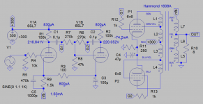
To make things simpler and easier for my first build, I opted to build a published design (DIY Push-Pull (PP) 6V6 / 6V6GT Tube Amplifier Schematic)
I powered it on the first time using a variac and when I hit 110 volts (or close to it), the fuse blew. I replaced the fuse and the next time I powered it up till I could hear music from the speakers. This was at 60volts and the B+ read 35-36volts. If I increased the ac voltage any further, the speakers started emitting a high pitched whine. I did not want to risk going any further since I didn't want to blow my only pair of test speakers (some old OEM car speakers). After this, I removed the power tubes (4 6v6gt Electro Harmonix) and powered it up using a variac all the way till 110volts and the fuse did not blow. B+ now read ~340volts.
Some of the online articles I read suggested to consider the possibility of a shorted tube but I don't have a tube tester to confirm. Short of ordering a new set of matched 6v6s, what else can I do? Or, should I be looking at diagnosing something else? I'd love to do do this myself and not take it to a tech since I do this only because I love building. I am in no hurry to get this fixed but want to learn from the experience.
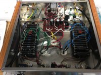
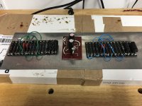
I've attached a few pictures of the build but understand that they may not be very helpful. I can take more pictures of specific sections of the amp if needed.
Thank you for helping out, I appreciate it. And, have a great weekend!
Note: Tubes were ordered from tubedepot, transformers from Angela, and rest of the components from Digikey and mouser. And, I bought a few other misc. components from hobby shops and a radioshack in Chicago.
I am hoping someone here can help me troubleshoot my first diy tube amp. I have built multiple speakers and subwoofers in the past but this was my first foray building an amp.
To make things simpler and easier for my first build, I opted to build a published design (DIY Push-Pull (PP) 6V6 / 6V6GT Tube Amplifier Schematic)
I powered it on the first time using a variac and when I hit 110 volts (or close to it), the fuse blew. I replaced the fuse and the next time I powered it up till I could hear music from the speakers. This was at 60volts and the B+ read 35-36volts. If I increased the ac voltage any further, the speakers started emitting a high pitched whine. I did not want to risk going any further since I didn't want to blow my only pair of test speakers (some old OEM car speakers). After this, I removed the power tubes (4 6v6gt Electro Harmonix) and powered it up using a variac all the way till 110volts and the fuse did not blow. B+ now read ~340volts.
Some of the online articles I read suggested to consider the possibility of a shorted tube but I don't have a tube tester to confirm. Short of ordering a new set of matched 6v6s, what else can I do? Or, should I be looking at diagnosing something else? I'd love to do do this myself and not take it to a tech since I do this only because I love building. I am in no hurry to get this fixed but want to learn from the experience.
I've attached a few pictures of the build but understand that they may not be very helpful. I can take more pictures of specific sections of the amp if needed.
Thank you for helping out, I appreciate it. And, have a great weekend!
Note: Tubes were ordered from tubedepot, transformers from Angela, and rest of the components from Digikey and mouser. And, I bought a few other misc. components from hobby shops and a radioshack in Chicago.
Attachments

Testing for shorted tube is easy with ohmmeter or simple continuity tester. The only pins that should show continuity are those connected to the filament. Anything else, the tube is shorted.
Since you pulled the tubes and the fuse didn't blow, your filter capacitors should be good, and the GZ34 should be good.
Then I would think the 6V6s are drawing too much current. With your variac at 60V there should be very little current through the 6v6s and the cathode should read just a few volts, I'm thinking less than 5, but probably 1 to 2. I'm thinking the shared cathode resistor should have about 11-14 volts on it when working properly.
While testing, I would use a dummy load, a 25 or so watt resistor on the speaker outputs.
On the 6V6 check pins 7 to 8, 8 to 5 and 3 to 4 for shorts.
Be careful around that B+. Don't touch the chassis or a ground while you are metering. Stick the black lead to the ground and put that hand behind your back.
Last edited:
Squealing is possibly positive feedback caused by the negative feedback line reversed. Disconnect the feedback, if that stops the whine, reverse the loudspeaker output wiring.
This sounds like possible positive feedback caused by the global feedback from the OPT secondary back to the input cathode. The feedback should be negative. The quickest way to test this is to reverse the plate wires from the output transformer to the 6V6s. With positive feedback the amplifier will be driven hard as an oscillator and can/will cause the fuse to blow. This is a common occurrence with first time power ups.If I increased the ac voltage any further, the speakers started emitting a high pitched whine.
This sounds like possible positive feedback caused by the global feedback from the OPT secondary back to the input cathode. The feedback should be negative. The quickest way to test this is to reverse the plate wires from the output transformer to the 6V6s. With positive feedback the amplifier will be driven hard as an oscillator and can/will cause the fuse to blow. This is a common occurrence with first time power ups.
HollowState,
Apologies if my question is stupid. I am trying to find my way around the schematic having self-trained myself reading books (Morgan Jones) and extensively reading through posts here (diyaudio).
When you suggest to reverse the plate wires from the o/p transformer to 6V6, is this the brown and blue wires on the 1608A going to the 6v6 plates? If that is the case, then should I also be reversing the screen wires (brown/yellow, and blue/yellow)? I am referring to the color schemes from this document (https://www.hammfg.com/files/parts/pdf/1608A.pdf)
Thanks!
I did not want to risk going any further since I didn't want to blow my only pair of test speakers (some old OEM car speakers).
dont worry abut your speakers .no need to check your 6v6s. when use tube rectifier like gz34 in power circuit ...if blew fuse ....first check the wiring and ac trans ....tube rectifier .
Yes, that is correct. Reverse both the plate and screen wires. doing so changes the phase relationship at the transformer secondary.When you suggest to reverse the plate wires from the o/p transformer to 6V6, is this the brown and blue wires on the 1608A going to the 6v6 plates? If that is the case, then should I also be reversing the screen wires (brown/yellow, and blue/yellow)? I am referring to the color schemes from this document (https://www.hammfg.com/files/parts/pdf/1608A.pdf)
Thanks!
I should have mentioned that earlier but forgot it was ultra-linear. Giving myself 3 lashes for that one.
HollowState's advice is spot-on. I ran into that exact problem with my first build back in 2001. It was built to that same schematic, except I used OPTs scrounged from an old Heathkit AA-151 I found cut in half at the dump. The first time I flipped the switch, the neighborhoods dogs went nuts for a few seconds before the fuse blew. After quick solder job with the OPT wiring - and a change of pants - all was well. Ah, the good ol' days...
Nice job, BTW. I really like the turret boards.
Nice job, BTW. I really like the turret boards.
Are you using bleeder resistors on your power supply caps?
They will wick heat from the fuse and stabilize current at fuse
They will wick heat from the fuse and stabilize current at fuse
Should sound interesting without grid rectification...but shouldnt pose a problem
Maybe a lpf on the input, case it really well then drop the values on the feedback hpf. The lack of grid rectification gives a interesting guitar amp warble. Can make one dizzy though...sweet!
Reminds me of how vampires talk in the movies.
Maybe a lpf on the input, case it really well then drop the values on the feedback hpf. The lack of grid rectification gives a interesting guitar amp warble. Can make one dizzy though...sweet!
Reminds me of how vampires talk in the movies.
Last edited:
I woukd suggest to power up only 1 amp.
If that one is ok (see checklist below), check the second (only the second)
If all is wel, connect both.
Without any tube inserted.
Do not forget to switch the amp off between each test (1..4)
Use a dummy load, R=4. 8 or 6 Ohm, 20 Watts about)
Do the following tests in that sequence and make a note of what you did and the voltages. Keep it as a reference for trouble shooting. You can not remember all these measurements...
0. Recheck the wiring of the whole amp. (amp is off, ac disconnected!)
1. Check the ac voltages on the secundary side.
2. Insert the GZ34 and check the dc voltages.
3. Insert the 6SL7 and check the dc voltages.
4. Insert both the 6V6's and check the dc voltages.
5. Connect a speaker and if it makes a high pitche noise, reverse the wires from the Output transformer as explained in a previous post.
It should work now unless your wiring is wrong.
Come back with the results.
Should sound interesting without grid rectification...but shouldnt pose a problem
Maybe a lpf on the input, case it really well then drop the values on the feedback hpf. The lack of grid rectification gives a interesting guitar amp warble. Can make one dizzy though...sweet!
Reminds me of how vampires talk in the movies.
I'am a little suspicious of gNFB that could load down the output, 1.5k and 100 ohms and 100u. If I use 6L6 in place of 6V6, the sim shows it oscillates.
Is the 6V6 cathode bypass electrolytic the right way round - positive to cathode? If not, it will short (and possibly explode) but in the meantime the 6V6 will draw far too much current.
?rellik said:Are you using bleeder resistors on your power supply caps?
They will wick heat from the fuse and stabilize current at fuse
Guys, thank you! I am amazed at the help I have received. I had to ferry the kids around yesterday and most of today... beautiful sunny weather to be out! Just got around to working on the amp today evening. I switched the plate and screen wires around and the amp works perfectly! No humming... I was very surprised. Must have got very lucky. B+ measures 315-320.
However, I plan to run some of the tests suggested in this post and make sure everything is fine. I really don't think I have a spot in the house to place this without the kids wanting to touch the tubes so I will use this extensively to learn more and hopefully set myself up for a future build that I have designed.
However, I plan to run some of the tests suggested in this post and make sure everything is fine. I really don't think I have a spot in the house to place this without the kids wanting to touch the tubes so I will use this extensively to learn more and hopefully set myself up for a future build that I have designed.
Yes, that is correct. Reverse both the plate and screen wires. doing so changes the phase relationship at the transformer secondary.
I should have mentioned that earlier but forgot it was ultra-linear. Giving myself 3 lashes for that one.
HollowState's advice is spot-on. I ran into that exact problem with my first build back in 2001. It was built to that same schematic, except I used OPTs scrounged from an old Heathkit AA-151 I found cut in half at the dump. The first time I flipped the switch, the neighborhoods dogs went nuts for a few seconds before the fuse blew. After quick solder job with the OPT wiring - and a change of pants - all was well. Ah, the good ol' days...
Nice job, BTW. I really like the turret boards.
Thank you again. I did exactly what you said and the amp works now.
Mr_Zenith, I enjoyed working on the turret boards. Got some parts from Tubedepot and designed the power supply board. The signal boards I did not design. Got them from Angela Instruments so could not plan the layout more efficiently. Learnt my lesson and designed the power supply board layout after that.
Are you using bleeder resistors on your power supply caps?
They will wick heat from the fuse and stabilize current at fuse
I am not. I made a couple of bleeder resistors with some 5k, 10 watt resistors lying around that I use before diving into the innards after powering down.
I believe the IEC plug I purchased has an inbuilt bleeder resistor. I checked the B+ and the power caps with a multimeter when powering down. And the readings fall rapidly from 320 to 2-4 within a minute or so.
- Status
- Not open for further replies.
- Home
- Amplifiers
- Tubes / Valves
- Help needed - DIY amp not working; first time powering up