hi guys,
does anyone have/know a link to find the following numbers:
Linear Exercursion - Xmax & Exercursion - Vd
for:
Vifa M25WO-49-08
and if possible Vifa C17WG-69-08, Vifa D26NC-15-06
thanks in advance,
Alex
does anyone have/know a link to find the following numbers:
Linear Exercursion - Xmax & Exercursion - Vd
for:
Vifa M25WO-49-08
and if possible Vifa C17WG-69-08, Vifa D26NC-15-06
thanks in advance,
Alex
that's where i've got everything so far except for Xmax and Vd, vifa don't state the xmax or vd
unless they are codewords for something else?
Alex
unless they are codewords for something else?
Alex
Hang on-got the figures right here. Take a moment to calculate.
Air Gap Height is part of the Xmax calculation. Will explain momentarily.
Air Gap Height is part of the Xmax calculation. Will explain momentarily.
First the formulas for Xmax and Vd
Xmax = maximum one way excursion-from center to extreme
Vd = Volume of air displaced, (moved), by the driver.
Sometimes Xmax is given as front-to-back linear travel, but it should be given as center-to-end.
Here are the formulas:
Xmax = maximum one way excursion-from center to extreme
Vd = Volume of air displaced, (moved), by the driver.
Sometimes Xmax is given as front-to-back linear travel, but it should be given as center-to-end.
Here are the formulas:
Attachments
For the Vifa M25W0-49-08:
The Effective Diaphragm Area, (Sd), = 346 square cm.
The Voice Coil Height is 14 mm. The Air Gap Height is 6 mm. Therefore, the Linear Xmax is (+ or -) 4 mm.
Therefore, Vd = 346 sq. cm times .4 cm = 138.4 cc.
For the Vifa C17WG-69-08:
The Effective Diaphragm Area, (Sd), = 143 sq. cm.
The Voice Coil Height is 12 mm. The Air Gap Height is 6 mm.
Therefore, the Linear Xmax = (+ or -) 3 mm.
Therefore, Vd = 143 sq. cm times .3 cm = 42.9 sq. cm.
For the Vifa D26NC-55-06, (the new substitute for the 26-15)
Effective Diaphragm Area, (Sd) = 7 sq. cm.
The Air Gap is longer than the Voice Coil by .5 mm. I assume that means it can move linearly (+ or -) .25 mm. Don't hold me to that. It's a tweeter anyway-things are different.
Estimated Vd = 7 sq cm times .025 cm = .175 cc.
By the way, mechanical Xmax for woofers is usually 1.5 to 2 times the Linear Xmax.
Do you have the response charts for the C17 WG? If not, they are located here:
http://www.mass.com.au/masssales/pdf/C17WG-69-08.pdf
I'll recheck the figures and edit if necessary. If I am off on the calculations, as an American I can blame it all on Metric!!
😉 😉
thanks,
now when the software calculates port sizes, when you chnage from 1 to 2 ports the length doubles plus a bit.
for e.g.
currently with one port 66mm diameter and 100.4mm long when i change to two ports @ 66mm diameter i get 249.1mm length.
now is the 249.1mm the total length for both ports or 2 ports @ 249.1mm length? being around 500mm total?
thanks,
Alex
yes i have the charts
The old tweeter and the new tweeter are the same, size and excursion-wise. No difference.
Good luck on your new project. Let us know how it turns out. Members are always posting pictures here.
Good luck on your new project. Let us know how it turns out. Members are always posting pictures here.
in loudspeaker lab 2, does it add the volume of the ports to the box volume? i guess it would but just checking, and i'll need to add the volume of the woofer also? (which is doesn't do) (x-o is seperated from speaker enclosure)
Alex
Alex
Boxes, braces, drivers etc. being unpredictable in size, shape and configuration cannot be included in program calculations. It's just not possible to anticipate every diyer's ideas. So the specified box is just the net volume -- one would have to add additional volume for ports (treated as solids), braces and so on 🙂
i'll add the voulme of the port then,
i thought they would include ports cause that's pretty easily implemented, anyhoo
few more adjustments and then i'm off for some mdf,
laterz,
Alex
i thought they would include ports cause that's pretty easily implemented, anyhoo
few more adjustments and then i'm off for some mdf,
laterz,
Alex
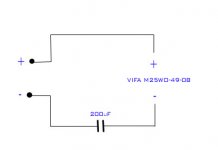
also for a temporary solution, unitl i get my HT amp and a real sub amp (1-3 months), i'm going to get a Y adapter and split my L+R audio from vcr/cdplayer/pc to two amps one will power my left+right speakers and the other the sub. I was told to turn treble to min and bass to 2/3 on the Subs amp (not a proper sub amp, just a normal amplifier/receiver). And get a 200uF Cap and put it between the amp and sub.
what's the correct diagram for this?
would this work?
do i need any resister or whatnot?
what's the correct diagram for this?
would this work?
do i need any resister or whatnot?
Attachments
Alex:
It'll work OK. It's a 6 dB/octave filter, you should be about 3 dB down at 100 Hz and go down 6 dB from there. The bass and treble controls will increase that.
If you have a multimeter, I can give you the URL of some freeware tone generators and you can go through the tones and measure how much voltage is going through your speaker at any given frequency.
The moderator of this very forum, Planet 10, has an extensive Transmission Line Enclosure website. One of the features there is an instruction sheet on how to set up a 6 dB or 12 dB filter between the source-(computer, CD player, whatever) and the amp-so your subwoofer does not need to have anything between it and the amp.
Speakers sound better when there is nothing between their terminals and the amp-no capacitors or inductors.
If you want to check it out, here is the link:
http://www.t-linespeakers.org/tech/filters/passiveHLxo.html
i have a tone generatior called sigjenny and a multimeter, but i rather do what you dais later in there
checking website atm,
Alex
checking website atm,
Alex
LOL, you can get SigJenny to work? It doesn't work on my computer.
Doesn't appear to be anything wrong with it, just not a match for my computer. 😀 😀
Doesn't appear to be anything wrong with it, just not a match for my computer. 😀 😀
- Status
- Not open for further replies.
- Home
- Loudspeakers
- Multi-Way
- help, need some figures