OMNI DCAND SHORT CIRCUIT PROTECTOR
http://www.diyaudio.com/forums/solid-state/65175-bora-nice-guy-serbia-yugoslavia-2.html;)
http://www.diyaudio.com/forums/solid-state/65175-bora-nice-guy-serbia-yugoslavia-2.html;)
Attachments
MT PROFESSIONAL H & AB CLASS POWER AMPLIFIERS
Hello
greetings anyone having schematics of these amplfier models h class or ab class models
warm regards
andrew lebon
Hello
greetings anyone having schematics of these amplfier models h class or ab class models
warm regards
andrew lebon
Thanks Vostro
I need amplifier protection for 1000w rms 8ohm amplifier AB class
short circuit protection on output of the amplifier its not for home use
Best Regards
A kilowatt into 8 ohms is a heck of an amplifier. As Sakis told you, the schematic you proposed will not survive at that kind of power in a pro sound environment. If you insist on building yourself, I suggest that you look for a design with many more output devices that already includes SOA protection for the output devices.
Making that kind of power requires lethal voltages on the rails. From your posts, it seems like you are fairly inexperienced. It would be much safer for you to start with a smaller amp. By the time you learn enough to build and blow up the proposed amp along with your speakers it would likely have been a lot less expensive to buy a good used amp of the desired power. Maybe even less expensive to buy a new amp.
Pro sound amps are usually a lot cheaper per watt than anything we can build ourselves. Stick to building home amps. 😉
I have built 2x800w rms 8ohm amplifier with 10MJ15003 10pcs per chanel
I have protection circuit for that amp but I dont know is it going to work on the amp I posted shematics its shunt resistor sensing circuit with temperature dc short protection and power on delay led indicators for all
Dont worry I was working with lethal voltages all my life tesla coils etc
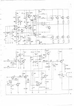
The schematics I posted is just for driver stage Im planing to put 14 pairs of output transistors 2c5200/2sa1943
Regards
Last edited:
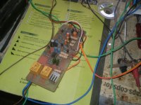
Here is the shematics of amplifier that I built 2x800w rms 8ohm with protection circuit 10x mj15003
How to connect this protection circuit with AB class amp that I posted schematics on the first page with 2sc5200/2sa1943
Protection circuit is under the amplifier circuit
Regards
How to connect this protection circuit with AB class amp that I posted schematics on the first page with 2sc5200/2sa1943
Protection circuit is under the amplifier circuit
Regards
Attachments
Last edited:
I didnt design that circuit I just found it on the net I just wanted to learn how to implement VI limiter on amplifier circuit but never mind
You did not say if you intend to actually build this amp. I don't consider it a very well thought out design even with the total lack of protection for itself or the load. Building an amp is only half the circuit. The mechanical construction can determine if it is an amp, 800W oscillator, or hum generator. If all you want is a big honking PA amp, buy a Behringer or something. Way cheaper, more efficient, works better, and has the protection worked out by the real designers in their lab.
I am working my way through the paper that was referenced. It has the answers. It was written for engineers by an engineer. This subject is not a DIY formula. It is engineering. You can't expect anyone here to give simple "do this" answers. Also look on the WIKI for a Baker Clamp. Read Self and Cordell.
I already have big transformer 3kw , 12 capacitors 10 000mf 100v 2 heatsinks 300mm
and want to make the amplifier Im good experienced in making pcb's
I can make other design AB class amplifier but I need advice on how to conect this protection circuit with amplifier I posted on the first page
Regards
Last edited:
I was thinking to connect this protection circuit with collector on upper rail and emiter on the second rail of the first output transistors
Or to connect protection E C outputs on emiter on first rail and emiter on second because its npn pnp and the power will flow that way
Or to connect protection E C outputs on emiter on first rail and emiter on second because its npn pnp and the power will flow that way
Last edited:
I can try and see how it can sense
to conect E with emitter on the first rail
but on the seccond rail collector is minus
where to connect C from protection on the amp
The only problem is that on the
second rail collector is minus connection
Maybe it will work that way
to conect E with emitter on the first rail
but on the seccond rail collector is minus
where to connect C from protection on the amp
The only problem is that on the
second rail collector is minus connection
Maybe it will work that way
Last edited:
You did not say if you intend to actually build this amp. I don't consider it a very well thought out design even with the total lack of protection for itself or the load. Building an amp is only half the circuit. The mechanical construction can determine if it is an amp, 800W oscillator, or hum generator. If all you want is a big honking PA amp, buy a Behringer or something. Way cheaper, more efficient, works better, and has the protection worked out by the real designers in their lab.
I am working my way through the paper that was referenced. It has the answers. It was written for engineers by an engineer. This subject is not a DIY formula. It is engineering. You can't expect anyone here to give simple "do this" answers. Also look on the WIKI for a Baker Clamp. Read Self and Cordell.
Building an amplifier is not a Rocket Science
Last edited:
Well, here's my two cents worth. I'm using this on a Phase Linear 400 and it works great, at least for DC protection and turn on "thump" delay...
The back to back 47uf caps should be at at least one quarter of one rail. They could potentially explode if the DC goes too high should a short occur, but are isolated by the 22 ohm resistors. (On the PL I upped them to 47k to help protect the circuit)
Also, you can use one DPST relay instead of two SPST as shown.
Attachments
Well, here's my two cents worth. I'm using this on a Phase Linear 400 and it works great, at least for DC protection and turn on "thump" delay...
The back to back 47uf caps should be at at least one quarter of one rail. They could potentially explode if the DC goes too high should a short occur, but are isolated by the 22 ohm resistors. (On the PL I upped them to 47k to help protect the circuit)
Also, you can use one DPST relay instead of two SPST as shown.
The back to back 47uf caps should be at at least one quarter of one rail. They could potentially explode if the DC goes too high should a short occur, but are isolated by the 22 ohm resistors. (On the PL I upped them to 47k to help protect the circuit)
Also, you can use one DPST relay instead of two SPST as shown.
Well, here's my two cents worth. I'm using this on a Phase Linear 400 and it works great, at least for DC protection and turn on "thump" delay...
The back to back 47uf caps should be at at least one quarter of one rail. They could potentially explode if the DC goes too high should a short occur, but are isolated by the 22 ohm resistors. (On the PL I upped them to 47k to help protect the circuit)
Also, you can use one DPST relay instead of two SPST as shown.
I this only DC protection and thurn on delay no short circuit protection for output transistors?
Regards
I already have big transformer 3kw , 12 capacitors 10 000mf 100v 2 heatsinks 300mm
and want to make the amplifier Im good experienced in making pcb's
I can make other design AB class amplifier but I need advice on how to conect this protection circuit with amplifier I posted on the first page
Regards
Before spending all the time and effort building this design, I seriously suggest you re-address the design first. I am no pro, a real new-be in amplifier design, but even I can see many issues I would address first. Start by reading Self and Cordell. Google "safe operating area". I am working my way through the Kiwanuka paper and it seems to have very good information.
I hate to mention this point, but it sounds like your scope of DIY is only the fab portion and you do not wish to tackle the engineering behind it. Even the mechanical construction matters a lot. You may be a pro at etching boards, but do you understand what issues are involved in layout to minimize distortion due to trace currents?
So You think that its bad amplifier design because it doesnt have VI limiters I can tell You that a lot of amplifiers do not have VI limiters protection and they work fine with fuse only as protection ,for short circuit protection can be placed on output rail and can protect amplifier from short on output.
Do You think this is bad design amplifier also
Regards
This driver can push up to 24 pairs of trasistors per channel
Attachments

Last edited:
short circuit protection
Hello
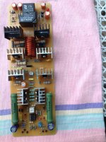
greetings jbl driver completed and tested nice sound but there are better
driver stage schematics much easier and better sound found this protection
while surfing does it look ok
warm regards
andrew lebon😉
Hello
greetings jbl driver completed and tested nice sound but there are better
driver stage schematics much easier and better sound found this protection
while surfing does it look ok
warm regards
andrew lebon😉
Attachments
Hello
greetings jbl driver completed and tested nice sound but there are better
driver stage schematics much easier and better sound found this protection
while surfing does it look ok
warm regards
andrew lebon😉
Is this short circuit protection?
That protection circuit looks strange its for stereo?
Thank You my friend
Last edited:
- Status
- Not open for further replies.
- Home
- Amplifiers
- Solid State
- Help need protection circuit for this amp