Hi Joe
Pic of powers supply
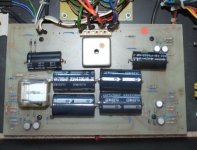
I think the way forward is to get the power supply working and protection cct working.
So back in with the relay, do not connect power to either channel. Then just switch on....see what happens. If it doesn't trip measure voltages. There are 2 voltages one for driver supply one for power transistor supply.Something like 27v and 34v.
If it does trip we need to troubleshoot power supply.
Pic of powers supply
I think the way forward is to get the power supply working and protection cct working.
So back in with the relay, do not connect power to either channel. Then just switch on....see what happens. If it doesn't trip measure voltages. There are 2 voltages one for driver supply one for power transistor supply.Something like 27v and 34v.
If it does trip we need to troubleshoot power supply.
Attachments
Hi Tony,
Sorry should have mentioned that the relay is actually back in. Ok no problem I’ll disconnect both boards this evening and see what happens. If nothing untoward I’ll connect the good one test again and then the duff one. That relay should close in protection mode shouldn’t it?
Thanks again
Joe
Sorry should have mentioned that the relay is actually back in. Ok no problem I’ll disconnect both boards this evening and see what happens. If nothing untoward I’ll connect the good one test again and then the duff one. That relay should close in protection mode shouldn’t it?
Thanks again
Joe
Hi Joe
Yes I think relay should close.
Looking at your ps board I think the connections to the amp pcb are 2 orange 2 black and one blue.
Presumably 2 x 34v 2x 27v 1 x earth.
Yes I think relay should close.
Looking at your ps board I think the connections to the amp pcb are 2 orange 2 black and one blue.
Presumably 2 x 34v 2x 27v 1 x earth.
Last edited:
Hi Joe
There should also be three more connections from psb to amp boards. These are sensors for the protect cct. Can't quite see those on your pic.
There should also be three more connections from psb to amp boards. These are sensors for the protect cct. Can't quite see those on your pic.
Hi Tony,
ok here's the results please see photo for orientation:
1) all connections to the boards removed - no relay activity at all on power on.
2 The following voltages are present:
+32V at LH orange wire
-32V at Blue wire
+27V at bottom orange wire
No -27 voltage at all on any wire.
All measurements taken with DMM black lead connected to speaker neg.
So I imagine the absent -27V is important - on the other amp is present and correct at the black wire. So why its AWOL on this one is beyond me?
Ref the additional connections: these are 2 x thin orange and 2 x thin black wires - these are above the big resistors. The thin blue looks like it comes of the ground(?) below these.
The only other wire is red which has a resistor in series and shows continuity with the ground speaker terminal.
So odder than an odd thing from oddsville.
Any thoughts are apprieciated.Thanks for your time.
Kind regards
Joe
Attachments
![IMG_1256[558].jpg](/community/data/attachments/769/769660-2f76831239657f6a91afbc58dcb24346.jpg?hash=L3aDEjllf2)
Hi Tony,
yes indeed - the fuse had blown. But on replaceing and rewiring - the protection circuit kicks in straight away.
If I remove all the wires on the no bias board - leaving the other board connected - the relay stays open. I also have -27V on that black wire.
So a continuing problem with the one amp board.
So the only components not changed on this board are the caps and one Large 10K resistor and the two 140 Transistors and the diodes, so I'll check these and see where I get.
When changing the resistors like for like values were placed so nothing odd there, so either one of the through board connections is off or shorting or the transistors or diodes are oc?
Thanks again for your time.
Ref the fuses - 5amp/250V 20mm OK or do you have slow blow in yours?
Joe
Hi Joe
Well some progress.
No fuses on my amp.
I suspect outputs suffered thermal runaway. I would perhaps check voltages across emitter resistors to determine either BD 203 or BD 204 are faulty.
Thought the fuses were 3.15amp.
Best of luck
Well some progress.
No fuses on my amp.
I suspect outputs suffered thermal runaway. I would perhaps check voltages across emitter resistors to determine either BD 203 or BD 204 are faulty.
Thought the fuses were 3.15amp.
Best of luck
Last edited:
Hi Tony,
on disassembly, BD203 and 204 showing signs of shorting out so replacing these just as a 1st step - then look into further problems tomorrow.
All the best
Joe
on disassembly, BD203 and 204 showing signs of shorting out so replacing these just as a 1st step - then look into further problems tomorrow.
All the best
Joe
Hi Joe,
Yes I thought they had failed.
What are the fuses protecting, output devices have protection cct which works quickly so why fuse failed?
Certainly I would check further before switching on again. Perhaps a DMM check on components compared with the good side.
With hindsight the 5 wires 2orange 2 black 1 blue are the protection cct sensors directly to emitter resistors
Very interesting amplifier and maybe dates from 1975ish.
Hi Tony,
well I think I'm almost there....
I couldn't tell you what those fuses protect, my knowledge in faultfinding is minimal and the psu board is a real horror to move about. Every time I've done it so far, the main transformer wires have come loose in their solder!. So I've borrowed a form of solution from your photos - the wires in your amp are nicely held in what look like screw connectors. I've managed to find something similar so will be fitting it to hopefully solve this problem once and for all. This way I'll be able to remove all the transformer wires and remove the board from the Amp without the chance of breakage.
So after replacing the 203 and 204, ( I have some 911/912 here as well - but just wanted to keep it as was for now), on power up that board fried the 2 100R resistors which run to its other BD140 transistors - the ones with the additional u shaped heatsink.
Now I had a complete board failure on the other amp due to one of these BD140's being duff, so I replaced both and the 100R's that had seen better days. As luck would have it, all now appears good. I have -27V at the black wire and the bias can be set although there is a difference between the 1R resistors. I think the info I have here says final check is at B, so I'll do that. I'd still like to rebuild all the boards with 1% metal films - the board I did had some interesting values on these. But thats a job for another day.
The bars that trap the transistors to the heatsinks still get really hot, So my job now is to add ventilation to that base panel. Oh, and hopefully finally get to hear them work....
Although I consider myself very much a novice at all this with limited knowledge - your kind help and advice makes me I feel I've had a bit of a result. Maybe these are a bit temperamental and time will tell on that one, but if they're anything like what I remember from my youth, they'll be worth the effort.
Thanks again Tony
Joe
Hi Joe,
Well thats a horrible job done well. Congrats.
The heat of this amp has always caused trouble. The heat sink is not very effecient being steel as opposed to ally.
You could turn down the bias, might still be OK on your speakers.
Or you could replace steel heatsink with ally heatsink.
I have three of these amps. One I keep as original and two I have replaced all resistors with Holco and capacitors with decent film types. I run these as monoblocks removing the power supply to one of the amp boards in each amplifier. Seriously satisfying.
Enjoy your amp.
Hi Tony,
apologies for not replying sooner - I've had my head in the Preamp.
Luckily I had a hole punch around here so I managed to get a few holes in the base and top cover of both amps. I didn't fancy any aluminium swarf floating around especially after the problems of late.
I got the preamp done so all the old carbon resistors are in the bin. Some were sort of Ok but others were quite out.
Mono - now theres a thing - If you've got the time please explain the procedure, I can't make head nor tale of the accounts I've found.
But as I mentioned before - they're a little less mystifying now.
Yes I think you're right these are from 1975 ish. I remember the Electrocompaniet agent coming to the Hifi shop I worked in years ago, with these - they were promptly connected to some Isobariks we had on display and the rest as they say is history. Excellent. Another amp on the wishlist would be the big Mission - 771/772 ( IIRC). They were nice too, but different animals to these.
Keep in touch and stay safe
Joe
Hi Tony,
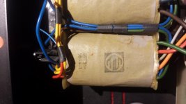
your transformer, does it have any information on it - one of mine has a pronounced buzz which lessens if the straps are made tighter. I wondered if repacements were available as the laminations have probably started to come loose?
Cheers
Joe
your transformer, does it have any information on it - one of mine has a pronounced buzz which lessens if the straps are made tighter. I wondered if repacements were available as the laminations have probably started to come loose?
Cheers
Joe
Thanks Tony
mines the same, I'll see what I can find out, if I get anything I'll let you know.
Joe
mines the same, I'll see what I can find out, if I get anything I'll let you know.
Joe
Hi Joe
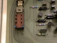
Never did bother with a preamp so not much help to you. Interesting pic though, those black resistors are I think Holco and would not be original. So somebody has been tweaking .
cheers
Tony
Never did bother with a preamp so not much help to you. Interesting pic though, those black resistors are I think Holco and would not be original. So somebody has been tweaking .
cheers
Tony
- Home
- Amplifiers
- Solid State
- Help need for Electrocompaniet The 2 channel amplifier