OK... I tried to attach an image.. but its in emf? format.
Simply put... the pre-amp was simulated with 2N3819's and BC547's.
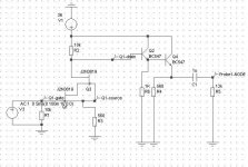
It has a cascode 2N3819 with a 560 ohm source resistor and a 10K drain resistor.
Running from a +36v supply... that places the upper 2N3819 drain at around 18v.
This is taken from this point into 3 paralleled BC547 emitter followers with a common 270 ohm resistor.
Output is taken from this point via a 1uf cap and a 10K load resistor.
Simulating the circuit... I get 0.0001% THD with 10v peak output at 1Khz.... but at 10Khz get 3.53% THD...
Why the huge difference?
Should I be running more current in the cascode?
btw... I need a voltage gain of 10.
Thanks!!!!
Simply put... the pre-amp was simulated with 2N3819's and BC547's.
It has a cascode 2N3819 with a 560 ohm source resistor and a 10K drain resistor.
Running from a +36v supply... that places the upper 2N3819 drain at around 18v.
This is taken from this point into 3 paralleled BC547 emitter followers with a common 270 ohm resistor.
Output is taken from this point via a 1uf cap and a 10K load resistor.
Simulating the circuit... I get 0.0001% THD with 10v peak output at 1Khz.... but at 10Khz get 3.53% THD...
Why the huge difference?
Should I be running more current in the cascode?
btw... I need a voltage gain of 10.
Thanks!!!!
Simulations
Hi Richard
First of all it would help with a schmatic
The THD simulation is difficult, since it's based on samples, and a FFT (Fast fourier transform) The problem is problably the simulator and not your amp. 🙂
Also the THD needs a center freq to do the calculations. What program do you use?
My experience is that simulations are less than perfect regarding THD, but a nice tool to make sure all your DC levels are right.
\Jens
yeah, we need a schematic.
and I think most of us have come to the conclusion that distortion numbers on a simulator are about as close to worthless as you can get. there was at least one thread on this a while back.
sorry 🙁
mlloyd1
and I think most of us have come to the conclusion that distortion numbers on a simulator are about as close to worthless as you can get. there was at least one thread on this a while back.
sorry 🙁
mlloyd1
Advantage?
The output darlington's don't really add a lot to THD I think... so what would be the advantage?
Would it be better to put one on the Source of the cascode?
Thanks!
The output darlington's don't really add a lot to THD I think... so what would be the advantage?
Would it be better to put one on the Source of the cascode?
Thanks!
split supply
oh... well since the source of the FETS are about 1v above ground.
And btw I changed the drain resistor to 12K and the source to 680. Better symmetrical clipping...
I would have to go with a split supply to build a CCS for the source of the input FETS.
I could try a CCS on the output NPN....
oh... well since the source of the FETS are about 1v above ground.
And btw I changed the drain resistor to 12K and the source to 680. Better symmetrical clipping...
I would have to go with a split supply to build a CCS for the source of the input FETS.
I could try a CCS on the output NPN....
CCS on output
Remember that I am simulating all of this... and don't have anything built..
the CCS didn't change anything wrt the 560 ohm resistor.
the simulated distortion is dominated by the input FETS.
Remember that I am simulating all of this... and don't have anything built..
the CCS didn't change anything wrt the 560 ohm resistor.
the simulated distortion is dominated by the input FETS.
I suppose you could cap couple the input and use a voltage divider to pull up the gate of the fet to avoid building a split supply.
Regards,
Jam
Regards,
Jam
confused?
What would increasing the voltage on the gate of the FET do?
Please explain!
p.s. This is kinda my first intro to JFETS and BJT... I have been designing with tubes and MOSFETS b4 now.
What would increasing the voltage on the gate of the FET do?
Please explain!
p.s. This is kinda my first intro to JFETS and BJT... I have been designing with tubes and MOSFETS b4 now.
The j fet is a depletion mode device so it self-bias but is limited as to how much voltage swing is allowed at the input. If you bias the input at a higher voltage, this will allow a wider voltage swing at the input before clipping.
Regards,
Jam
Regards,
Jam
THD figures
Run a transient analysis... display the curve and select it. Its under the 'Measure' menu on that window.... select transient and select distortion full.
something like that anyway...
you can also do a FFT on it and see how the THD spectra looks like.
Simulated this circuit has a nice distortion progression.... dominated by 2nd until close to clipping then 3rd creeps in.
🙂
- Status
- Not open for further replies.
- Home
- Amplifiers
- Solid State
- Help me with my JFET / BJT design