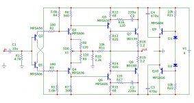
I don't know any electronics or amp engineering, but I've been after an all discrete portable headphone amp, having tried a number of different opamps but never been totally satisfied with any of them. There's very little interest in this kind of amp in the DIY-world, so I've done some tweaking. I think I like bipolars better than JFETs, so I merged the front end of Hiragas le Classe A with the output stage of JISBOS by steinchen/amb. I've only built one channel. It's actually playing music, seems fairly stable, not much offset drift, very low noise. I'd prefer a low supply so I can use AAA's (9-12V) and have the amp class A biased. An alternative is class AB biasing and use 2x9V batteries. The different transistors is because I had matched pairs of BC327/337/549/559. I guess it would be nicer to use only BC550/560 and BD139/140. Some of the resistor values are are taken from the original circuits, some found by trial and error and some just randomly choosen.
I'm not clever enough to simulate circuits, so I don't know if there are major errors.
Can this be made into a good sounding amp? Can you help me with it? I would like to make it with an active ground channel, so this channel should be unity gain. Could it be made unity gain stable?
Please help me make this become a functional and hopefully good sounding amp!
An externally hosted image should be here but it was not working when we last tested it.
nelsonvandal said:I don't know any electronics or amp engineering,...
You certainly know the jargon😀 You managed to match transistors, measure offset, bias it...

So what exactly do you want help with, its working, it is stable. there is little noise, what does it sound like?

Re: Re: Help me with headphone "le Classe A"
E g the feedback resistors is just more or less randomly choosen. Would higher or lower values make any difference if the proportions are the same?
R19 and R20 wasn't used in the amp I "copied", but they made the amp more stable at lower gain. It oscillated like hell at unity gain. The values are just randomly choosen, should I try other values? Should I even use these resistors?
Are biases to Q1-Q6 enough for class A operation? The current draw isn't more than about 5 mA for all of them.
Will BW-limiting caps make the amp more stable, and where should I put them if needed - parallell with R19/R20 or parallell with R11 or between base and collector of Q3/Q4 or Q5/Q6?
In le Classe A R9/R10 aren't used. Will Q5/Q6 add gain now? I added those resistors because of massive current draw otherwise.
Is it likely this could be unity gain stable?
What do you think the output swing is? Is it complicated to calculate? What could the open loop gain be?
It's always hard to tell how it sounds when it's mono. There are no obvious flaws. Even with 9 V supply, it plays very loud without clipping. I wanted to know if there are any major errors, and was hoping someone could lead me in the right direction before I make a real amp out of it. Is the amp sane or not?Nico Ras said:So what exactly do you want help with, its working, it is stable. there is little noise, what does it sound like?
E g the feedback resistors is just more or less randomly choosen. Would higher or lower values make any difference if the proportions are the same?
R19 and R20 wasn't used in the amp I "copied", but they made the amp more stable at lower gain. It oscillated like hell at unity gain. The values are just randomly choosen, should I try other values? Should I even use these resistors?
Are biases to Q1-Q6 enough for class A operation? The current draw isn't more than about 5 mA for all of them.
Will BW-limiting caps make the amp more stable, and where should I put them if needed - parallell with R19/R20 or parallell with R11 or between base and collector of Q3/Q4 or Q5/Q6?
In le Classe A R9/R10 aren't used. Will Q5/Q6 add gain now? I added those resistors because of massive current draw otherwise.
Is it likely this could be unity gain stable?
What do you think the output swing is? Is it complicated to calculate? What could the open loop gain be?
The wires shouldn't be shorted of course. I thought the JFETs could do some good isolating the rails of the small transistors from the output transistors to increase the rejection ratio. It seems like they actually do. Since I don't have an oscilloscope, I have to listen to the rails, and there's lower "noise" on those rails now. Maybe they shouldn't be there at all, maybe I should use some other kind of CCS. What do you think?Nico Ras said:What is the purpose of Q9 an Q10, it looks like all the wires are shorted?
nelsonvandal said:
The wires shouldn't be shorted of course. I thought the JFETs could do some good isolating the rails of the small transistors from the output transistors to increase the rejection ratio. It seems like they actually do. Since I don't have an oscilloscope, I have to listen to the rails, and there's lower "noise" on those rails now. Maybe they shouldn't be there at all, maybe I should use some other kind of CCS. What do you think?
There, fixed. A zero volt generator to the right. Works off 9V. Biased in class A bias current approximately 85 mA. should be loud enough with 3V p-p swing.

Attachments
Nico Ras said:
There, fixed. A zero volt generator to the right. Works off 9V. Biased in class A bias current approximately 85 mA. should be loud enough with 3V p-p swing.
Knocked one channel up, and it actually sound great! Not a bad design you started out with.

Wow, that was quick! I'm really glad someone like you are helping me with this. Have you done any simulations or measurements?
Just some questions before I go ahead with it and buy the stuff that's needed. Since I want it portable, I'd really want a bit lower current draw to something like 20-30 mA/channel, both because of run time and not having to use large heat sinks. I use 300 Ohm sennheisers and almost never listen louder than 2 V, so I don't think I'll need all that current.
Could the bias be tuned down by changing R13/R14 and R16/R17, and to what values? I think using resistors like in your schematic is more attractive since it's cheaper and takes up less space, but is it still possible to use a VBE multiplier for bias adjustment, and are there other drawbacks of using one? Maybe I could have a switch for high or low current. Are those resistors forming some kind of local feedback loops? You see, I don't know much about this stuff. I just want a pure uncolored nonfatiguing sound.
Will I get a worse result using BC549/559, BC550/560, BC327/337, BD137/138. I have a lot of them lying around.
The circuit to the right - is it a virtual ground circuit? Should it be one of those/channel or one for the whole amplifier? What about output impedance? I'm a fan of active ground channel with very low output impedance for less crosstalk. I think the ground channel is equally important to left/right. Could I still use this amp as an active ground channel after a railsplitter/virtual ground?
PSRR, is it something to worry about in a class A amp with active ground? Should the rails to the amplifying stage be isolated?
nelsonvandal said:Wow, that was quick! I'm really glad someone like you are helping me with this. Have you done any simulations or measurements?.....
Sorry mate, I read somewhere 32 Ohms. I was wrong. I will reduce bias.
Yes I have simulated it, it looks pretty good. Transistor types are not that important now, knock it up with what you got just to satisfy yourself first. I use MPSA types because I have hundreds. You can use your BC types throughout, even for the output they will run a little warm at about 135 mW, but well within general purpose low power types.
To lower bias to about 25 mA, change R12 & R15 to 120 ohm. If the gain is too low or too high change R10, I did not know what sensitivity you need.
Of course class A draws a constant current from the supply so NiMH rechargeable batteries would work nice as they are designed for deep cycling. You want to know more about charging, e-mail me I don't think this forum is for battery chargers.
Furthermore power supply rejection is not really an issue for batteries and class A. If you want to use a power supply, just use a 9V regulator.
Almost any 9V transformer will work, you need less than 1VA. You get little encapsulated PCB types that is great for the job.
e-mail me I will send the simulations, it is too much trouble to post here.
BTW I am impressed enough with the simulation I am starting to lay a PCB to build it. I am using a single ended class A at the moment (earlier posts) but I like what I see. I also use HD650. Would you be interested in a PCB layout. If yes what format you want it in?
I am thinking of using surface mount throughout it will cost almost nothing and it will fit into a little pocket box available from OKW in Germany, I have a few in my drawer.
I am thinking of using surface mount throughout it will cost almost nothing and it will fit into a little pocket box available from OKW in Germany, I have a few in my drawer.
Spending time and energy on this is very generous, I'm grateful. I would like this amp as small as possible. SMD is fine with me except for transistors maybe. It's easier to find through-hole transistors here in Sweden, and they're easy to measure for Hfe in a standard multimeter. Or is matching not crucial? Are you thinking of something like BC850/860 and BCX53/56? Those I can find at my local vendor ELFA.Nico Ras said:BTW I am impressed enough with the simulation I am starting to lay a PCB to build it. I am using a single ended class A at the moment (earlier posts) but I like what I see. I also use HD650. Would you be interested in a PCB layout. If yes what format you want it in?
I am thinking of using surface mount throughout it will cost almost nothing and it will fit into a little pocket box available from OKW in Germany, I have a few in my drawer.
I was planning on using a Hammond 1455J1201 http://www.elfa.se/pdf/50/05043815.pdf because I have one unused. I don't want an amp larger than this. It should fit a standard jeans pocket. With only 8 AAA's I think I can fit 3 channels if I use an Alps RK097 pot and SMD 3.5 mm jacks (or RCA for input).
I've crammed 3 JISBOS channels (discrete JFET-input buffer similar to this circuit), a LM317 as charger and 10 AAA's in a C1201 before, but that's too tight to be safe and makes it very unfriendly to modify.
E-mail sent, ofcourse I want to see the simulations!
BTW, what do you think of active ground channel. Like I said, I think it improves the sound compared to caps/resistor divider or using center point of the batteries. I think I'd like this amp with a low impedance ground channel.
nelsonvandal said:
Spending time and energy on this is very generous, I'm grateful. I would like this amp as small as possible. SMD is fine with me except for transistors maybe. It's easier to find through-hole transistors here in Sweden, and they're easy to measure for Hfe in a standard multimeter. Or is matching not crucial? Are you thinking of something like BC850/860 and BCX53/56? Those I can find at my local vendor ELFA.
I was planning on using a Hammond 1455J1201 http://www.elfa.se/pdf/50/05043815.pdf because I have one unused. I don't want an amp larger than this. It should fit a standard jeans pocket. With only 8 AAA's I think I can fit 3 channels if I use an Alps RK097 pot and SMD 3.5 mm jacks (or RCA for input).
I've crammed 3 JISBOS channels (discrete JFET-input buffer similar to this circuit), a LM317 as charger and 10 AAA's in a C1201 before, but that's too tight to be safe and makes it very unfriendly to modify.
E-mail sent, ofcourse I want to see the simulations!
BTW, what do you think of active ground channel. Like I said, I think it improves the sound compared to caps/resistor divider or using center point of the batteries. I think I'd like this amp with a low impedance ground channel.
I looked at the box and think it is quite possible to fit the PCB. I am not so confident in active ground, this is really something that confuses me.
Nobody could yet explain the benefits other than it costing three amps, personally I do not have any regard for amplifying the ground reference.
If you are talking differential then I would agree with common mode rejection, but there is nothing differential about the concept of placing an amp in the "ground" line.
Thank you for the mail.
Regarding ground, this is very hard for me to comprehend, sinking and sourcing current and all that. I think these measurements/simulations by amb posted at head-fi.org and headwize.com supports that using active ground vs. passive makes a difference.
http://www.head-fi.org/forums/3567005-post21.html
http://headwize.com/ubb/showpost.php?fnum=3&tid=7157&pid=63998&fpage=1
Since it has been a debate about it for a long time, everybody aren't convinced that it's for the better. I like this ground channel concept, but I'm not sure that separating virtual ground and small current returns from headphones return is equally important.
nelsonvandal said:Thank you for the mail.
Regarding ground, this is very hard for me to comprehend, sinking and sourcing current and all that. I think these measurements/simulations by amb posted at head-fi.org and headwize.com supports that using active ground vs. passive makes a difference.
http://www.head-fi.org/forums/3567005-post21.html
http://headwize.com/ubb/showpost.php?fnum=3&tid=7157&pid=63998&fpage=1
Since it has been a debate about it for a long time, everybody aren't convinced that it's for the better. I like this ground channel concept, but I'm not sure that separating virtual ground and small current returns from headphones return is equally important.
Hi Magnus,
when I set out designing my headphone amplifiers, I did read all this and I beg every-ones pardon that subscribes to this idea, personally I think it is rubbish.
It follows the same argument as wires that has polarity and crystal structure that need to be north south facing. Besides which channel's ground does it reference, the left input or the right or the amp?
If anything it may produce the effect of widening the stereo image, which for headphone listening is not a good idea anyway.
Kind regards
Nico
I've got a pair of questions for Nico Ras if he doesn't mind...
- what is the purpose of C2-C3/R16-R17 ?
- Did you run any sims in class-AB biasing ? Class A and portable don't sound too fun to me, especially with low impedance cans.
- what about replacing the input stage by a pair of complementary jfets ?
On the topic of ground channel, it could be argued that the advantage of a reduced crosstalk is to let you in charge of deciding how much "crossfeed" effect you want...
Thanks in advance.
I think the use of an active ground could make a measurable difference. All audio has to run through the ground return, and an actively driven ground channel makes sense to me. Whether it's audible is another matter. I would definitely avoid the split capacitor passive ground I have seen, for instance, in the original "Cmoy" amp.
I would just make a three-channel version and try it with and without the active ground. This circuit is so inexpensive anyway, just build an extra PCB.
I would just make a three-channel version and try it with and without the active ground. This circuit is so inexpensive anyway, just build an extra PCB.
paulb said:I think the use of an active ground could make a measurable difference. All audio has to run through the ground return, and an actively driven ground channel makes sense to me. Whether it's audible is another matter. I would definitely avoid the split capacitor passive ground I have seen, for instance, in the original "Cmoy" amp.
I would just make a three-channel version and try it with and without the active ground. This circuit is so inexpensive anyway, just build an extra PCB.
Still does not tell me what an active ground does only that you say it makes a measurable difference, what are you measuring? Is it phase, noise, linearity, what should I be looking for to "make a measurable difference".
If this was such a sonic improvement why is it not applied across all audio? Come to think of it, if I want a 50 watt class A, this is not just an extra PCB, besides what about the ground in the source, it is not an active ground. 😕
Also you would need a selector switch that would select the ground from the input sources as well so that an unselected input does not affect the selected ground. Personally, I am still unconvinced.

in the specific case of Class A operation and 300 Ohm headphone load the consideration of "active ground" is particularly hard to understand when the midpoint of the battery stack is available
Class A operation means that any possible common ground impedance signals will be linear, with the high 300 Ohm impedance loads the common gnd plane potentials could be µV, the paranoid could use both power planes of a 4-layer board for gnd
careful layout of the input and feedback gnds relative to the output connector gnd pin and output/battery return path should be able to keep common gnd path coupling on the pcb much less than the unavoidable coupling from the common gnd contact impedance of the TRS phone jack-plug interface R at 5-15 mOhm/300 Ohm ~= -90 dB (unavoidable as in "active gnd" topology doesn't help beat this limit either)
discrete amps with poor psrr may have greater coupling from the rails, in this one case a active gnd channel amp that exactly matched psrr with the signal channel amps could reduce channel-channel crosstalk - at a cost of doubled power drain - not good for battery operation
a few Qs spent on increased psrr in each channel amp would be a much cheaper approach
I wasn't trying to unconvince you. From a theoretical standpoint, I can't see how there is anything to gain.Nico Ras said:
Personally, I am still unconvinced.
I think it might be a way to get around something that is not a "careful layout." For amateurs it may result in better sound because of their inexperience with layout. Also, a high-end Technics amp I am currently disassembling uses this for some of its low-level circuitry, and I think it probably solved some kind of ground loop issue for them.
Regardless, it's easy enough to tell if it makes an audible difference or not.
Oh yes, Class A is lots of fun. We all do this for the sound quality, don't we? There's a depth and kind of golden sound especially in the mids that's lost with class AB, I think. The problem is everybody seem to think a portable amp have to use 9V batteries, and preferably 2x9V because of "reserve for transients". I don't need more than 2 - 3 V output for my 300 Ohm Sennheisers, and a lot less using IEM's. I can't see how a CDP or DAP could output transient voltage above that. A voltage swing of 2 - 3 V is all I need. Seven AAA's doesn't take that much more space compared to a 9V and let you go from class AB to A with the same runtime. If this amp is tuned to consume 30 mA/channel, there would be a theoretical runtime of about 15 h (with 2 ch or 10 h with 3 ch) , isn't that good enough? If you want a good opamp based class AB amp you should use AD797 with diamond buffers. With 2 channels thats 8 mA x 2 for the opamps + 6 mA x 2 for the buffers (if biased low, the ones I use draws about 9 mA) = 28 mA. With 2 x 9V batteries that's a runtime of about 9 h using the best batteries (quiescent only, less if you play it loud).00940 said:Class A and portable don't sound too fun to me, especially with low impedance cans.
I wanted bipolars all the way, because I believe bipolars sound better, and they're also cheaper and easier to find. My experience is mostly from using opamps, and I don't know if these findings are true for discretes, or if they're true at all. I have listened to a lot of different opamps and I find the biploar input ones sound smoother and more natural, eg AD797, AD829, ADA4841, LM6171, LM4562. JFET input opamps sound a bit grainy and harsh, eg OPA2134, OPA2107, AD8620, AD823, AD744, and they are fatiguing for long time listening. There are some exceptions to the rule, but these are my general findings.- what about replacing the input stage by a pair of complementary jfets ?
Thanks in advance.
- Status
- Not open for further replies.
- Home
- Amplifiers
- Headphone Systems
- Help me with headphone "le Classe A"