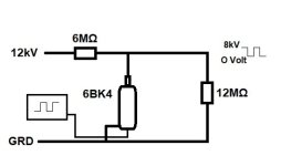
I have put together a HV pulse circuit using a 6BK4C.
This is my first tube circuit, so just a beginner when it comes to tubes.
I want an understanding of the tube and how hard I can push this 6BK4,
I'm using it at 12kV, well under the maximum spec.
Does that fact allow me to raise the maximum current at all?
The spec sheets says, "Under Maximum ratings",
'DC plate Voltage' 27,000 Volts,
But then says 'Unregulated DC Supply Voltage' 60,000 Volts.
I don't understand the difference?
Then I see 'Average Plate Current' 1.6Ma, does that mean if I have a 50% duty cycle, I can go to 3.2ma during the conduction time?
The next spec is 'Plate Dissipation' 40 watts, Is that plate Voltage times plate current?
Meaning, 40 Watts / 12,000V = 3.33ma plate current?
Then at the bottom of the specsheet there is a note;
* series impedance should be used with cathode to limit cathode current under prolonged short-circuit conditions to under 450ma.
Confusing, when the maximum is 1.6ma!
I've attached a simplified circuit diagram, but it's not much more complicated.
My basic question, I'm pushing the plate current spec a little, how much can I get away with?
Thanks for the help, Mikek
The specsheet is here, https://www.rfwiz.com/6el4a-6bk4c-ge-vacuum-tube
Attachments
Tubes are rated for their plate power dissipation. The power dissipation for pulse load is usually higher and must be verified from tube data sheet.
Make sure you are looking at the correct manufacturer data sheet including model suffixes and external material and measurements.
Tubes with same model numbers with different mechanical construction or manufacturer will not have same specifications.
This being a HV tube, will also have the grid dissipation in watts.
Regards.
The Tube I have is a Raytheon 6BK4C, I don't find a spec-sheet for that brand of tube.
So, I'm stuck using the GE or RCA specs. I see nothing about a pulse power dissipation spec.
If I make the assumption that the Raytheon tube has specs at least as high as the others,
I still have all of the questions I posted above.
Thanks, for your input, Mikek
So, I'm stuck using the GE or RCA specs. I see nothing about a pulse power dissipation spec.
If I make the assumption that the Raytheon tube has specs at least as high as the others,
I still have all of the questions I posted above.
Thanks, for your input, Mikek
'DC plate Voltage' 27,000 Volts,
"maximum voltage that can appear between plate and cathode"
Unregulated DC Supply Voltage' 60,000 Volts.
Maximum power supply voltage in the system.
The manufacturer of HV tubes always will assist in your work.
Talk to them, get safety documentation and carefully proceed your work.
If you are unsure of any step, stop the work, talk to supplier again until you are clear.
You should not be asking any questions on HV equipment build in a forum.
Not fully understanding your requirement, any advise in forum could be dangerous to your life.
Some of the systems I have seen ...Just for your reference...
HV systems are always associated with large RF interference, creeps, flashovers and corona discharges.
Have good x-ray shield (lead) if the supply voltage exceed 6 KV.
Have filament wiring done with lead shield cables and shield grounded.
Have the complete equipment must be inside a metal enclosure with a circuit breaker interlocked to the door.
Have 4 or more screws to open the door. Some additionally have simple pad locks. .., gives the person more time to think on what he is doing.
Have HV warning signs on the door.
Have dual copper flat ribbon grounding at two different points to the enclosure, all moving parts of the door are also grounded
(The user should never be able to turn on the power if the protection door is open.)
Did not have any DC filter capacitors for power supply. (no charge to hold)
Have voltmeters that are specified for HV measurements. HV creep would burn the meter.
First work on the safety aspects and then decide further.
If in doubt, ask the manufacturer for more safe procedures.
(If you did not have any doubt, just stop the work and do some other job like fishing)
Take care and consult factory.
Regards.
Good luck asking a manufacturer for help when a part hasn't been made in 40 years! And Raytheon probably wasn't the manufacturer anyway.
Heater current is 200 mA - must be limited to less than 450 mA (this suggests that heater voltage possibly could be increased to increase emission (increase current, decrease saturation voltage) but it's obviously operating outside specified parameters. The 27KV rating is while conducting; 60KV is "off". Dissipation (V x A) rating is average, at least to some maximum pulse length (might be fractional to whole seconds).
Heater current is 200 mA - must be limited to less than 450 mA (this suggests that heater voltage possibly could be increased to increase emission (increase current, decrease saturation voltage) but it's obviously operating outside specified parameters. The 27KV rating is while conducting; 60KV is "off". Dissipation (V x A) rating is average, at least to some maximum pulse length (might be fractional to whole seconds).

The 6BK4C tube (the C at the end is important) is a shunt regulator for high voltage color TV sets. It has become popular for miscellaneous HV applications because the x-ray emission is lower than similar tubes due to thick lead glass, and it was inexpensive back then. It is not anymore today, because it is a sought-after spare part for HV lab power supplies and voltmeters. As example, on Wireless World march 1971 issue there is a project of a 50KV vacuum tube voltmeter based on the 6BK4C. Back to the original questions, I believe that power dissipation is conservatively declared on the datasheet because the original application was meant for a placement in a poorly ventilated enclosed case. Better ventilation and maybe a fan will help. This tube was not specified to work as a switch so it is undetermined if a 50% duty cycle may enable a doubling of the current. I would think so, altough increasing the current above a critical point may damage the emissive cathode material so I would limit the increase to maybe 50%. I am guessing that the 450ma warning has been put there because the filament voltage may have been derived from line transformer auxiliary windings, and therefore it may briefly spike at 12V or more at fault conditions. It can be ignored if the filament voltage is coming from a standard transformer, this warning is indeed missing on my Sylvania datasheet. Remember that most transformers are limited to 2000V insulation between primary and secundary windings. By the way, the x-ray emission is low but not enough to avoid a shield.
Attachments
Last edited:
Supply voltage up to 60 kV under the condition that voltage drop in the tube (acting as series regulator) does not exceed 27 kV. For example, input voltage 60 kV, output voltage 33 kV, tube drop 27 kV.
Maximum plate dissipation is averaged over time. Instantaneous power in impulse could be hundreds of times higher than that.
Same with plate current, maximum averaged over time. Peak instantaneous current in impulse is usually specified for a given impulse duration or duty cycle. 450 mA here is the maximum allowed instantaneous current. 1.6 mA average current should not be exceeded, even though plate dissipation limit would allow it. Higher than specified maximum plate current will cause cathode stripping and dramatic reduction of tube's life.
As I typed, the page did not refresh in time and was unable to see this reply.Good luck asking a manufacturer for help when a part hasn't been made in 40 years! And Raytheon probably wasn't the manufacturer anyway.
Regards.
The 450mA relates to the attached condition in the 6EL4A datasheet. The 450mA is from an internal arc with a relatively benign voltage across the arc (as the heater shouldn't be more than 450V negative to the cathode) and not due to an anode related current of 450mA (which has the 1.5mA average limit). As a sanity check note that if the 6.3Vac heater was at -450V, and it shorted to the cathode, the 1k cathode resistance would limit the heater arc current to 450V/1k = 450mA. Such a fault current should be at least fused such that any fault is 'momentary', as described in the notes.
Note that the application is for a shunt regulator, where the anode current will be constant, with a 1.5mA max limit capability. There is no duty cycle allowance for > 1.5mA, or is there a surge or momentary rating, so you go into unchartered territory if you somehow have a surge, or transient or pulse or fault in your load.
Although there is only one pre-condition for power turn on, I would suggest you use a heater pre-start or at least identify and assess some commercial equipment as to whether they use a heater pre-start.
Attachments
You are probably good with the 3.2ma 50% duty cycle use. Increased cathode current wears the cathode at some point.
The 6bk4 was used for hours with about 1 ma cathode current.
How many houra do you plan to use this device?
The 6bk4 was used for hours with about 1 ma cathode current.
How many houra do you plan to use this device?
- Home
- Amplifiers
- Tubes / Valves
- Help me understand Tube maximum specs