Hi
I want to design a reclocker that is based on typical TTL IC's and a very basic one. I do not nessesary need low jitter, rather a real PLL reclocking based on data bits, not preamble (like in cs8414 or so..)
I am not sure what is the way to amplify SPDIF signal to TTL level as well as wheather I need a frequency divider in PLL.
Please help!
best regards
Adam
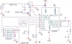
To bring SPDIF to TTL the easiest way is to use 74HCU04 inverters AC coupled at the input with 100n CAP then bias the HCU04s into linear operation by using an input resitor of say 1K and a feedback resistor of 10K. (you may need to optimise these values) Cascade two or three of these to bring the signal up to TTL levels.
The U in HCU04 means they are unbuffered and hence can operate as linear amplifers.
As for using the HC4046 it is well documented in the data sheet first read this. You should be able to set the VCO to operate at 256x Fs (11.2896MHz) and I would use phase comparitor 2. Its the most difficult to get working well but it is much lower noise than the others.
You will need to use an external divider to match the VCO freq to your incomming data frequency. ( I think this is 2.8224MHz approx for SPDIF but I could have remebered it wrong i.e you need to divide by 4)
Not quite sure why you want to do this but this should give you a very jittery but phase locked clock.
Regards,
Andrew
Thanks Andrew
That's exactly what I want: low data-induced jitter rejection to check transmission media impact on sound.
regards
Adam
That's exactly what I want: low data-induced jitter rejection to check transmission media impact on sound.
regards
Adam
I'm sure you already came across the following, which basically allows you to hit the ground running.
Philips design software 74HCT4046/7046/9046
http://www.standardics.nxp.com/support/pll/pll.zip
Best regards,
Sander Sassen
http://www.hardwareanalysis.com
Philips design software 74HCT4046/7046/9046
http://www.standardics.nxp.com/support/pll/pll.zip
Best regards,
Sander Sassen
http://www.hardwareanalysis.com
darkfenriz said:
Please comment.
You have actually read the SPDIF specification ?
By AES? Not whole, why do you ask?
If something's wrong, than well, If you could help, this ehhmm... would be some kind of ? helpful...
If something's wrong, than well, If you could help, this ehhmm... would be some kind of ? helpful...
darkfenriz said:By AES? Not whole, why do you ask?
If something's wrong, than well, If you could help, this ehhmm... would be some kind of ? helpful...
There are minor design errors and there are Tacoma Narrows sized errors. Your error is so fundamental, the only thing I can say is read and understand the specification
darkfenriz said:Read the specification, datasheets of receivers and Hawksford's publication.
No clue...
The datastream has the clock embedded in it, is biphase mark encoded and uses code violations to define the channel boundaries.
Which particular edge do you plan to lock to and what do you intend to use as a reference ?
darkfenriz said:Hi
I want to design a reclocker that is based on typical TTL IC's and a very basic one. I do not nessesary need low jitter, rather a real PLL reclocking based on data bits, not preamble (like in cs8414 or so..)
I am not sure what is the way to amplify SPDIF signal to TTL level as well as wheather I need a frequency divider in PLL.
Please help!
best regards
Adam
H Adam,
If you want something that works, and is very good in performance, copy the PLL / VCXO section of this DAC design
http://www.tentlabs.com/Products/Components/DIYDAC/index.html
the x046 series of PLL's is soso for serious audio
best
Re: Re: Help me design a SPDIF reclocker, preferably based on 74hc4046
It won't make the slightest difference, it still won't work. From the diagram in post #5, the OP is trying to work with the raw SPDIF datastream.
Guido Tent said:
H Adam,
If you want something that works, and is very good in performance, copy the PLL / VCXO section of this DAC design
http://www.tentlabs.com/Products/Components/DIYDAC/index.html
the x046 series of PLL's is soso for serious audio
best
It won't make the slightest difference, it still won't work. From the diagram in post #5, the OP is trying to work with the raw SPDIF datastream.
Re: Re: Re: Help me design a SPDIF reclocker, preferably based on 74hc4046
I know that OP's crcuit won't work, that is why refered him to a proven design. That uses a 8412 to abstract a bitclock from the SPDIF and then put it in a PLL......
best
rfbrw said:
It won't make the slightest difference, it still won't work. From the diagram in post #5, the OP is trying to work with the raw SPDIF datastream.
I know that OP's crcuit won't work, that is why refered him to a proven design. That uses a 8412 to abstract a bitclock from the SPDIF and then put it in a PLL......
best
That's right, silly me,
I knew it is BMC coding, but didn't suspect it is impossible to directly reclock with a PLL, my experience with clock recovery circuits is very poor.
Thank you for pointing this.
Any idea how to make it work with general purpose devices?
I knew it is BMC coding, but didn't suspect it is impossible to directly reclock with a PLL, my experience with clock recovery circuits is very poor.
Thank you for pointing this.
Any idea how to make it work with general purpose devices?
darkfenriz said:OK
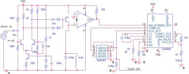
I've changed the schematic, so that it should work now.
I've included a "rectify and filter" front end, which I designed with friend for E1 stream (HDB-3 encoded) about a year ago.
What do you think of it?
Thank you all
Bipolar /= Biphase.
rfbrw said:How ?
Clock recovery by filter method, which consists of symetrizing, derivation, rectification and filtering. And followed by the PLL with frequency multiplier. Do I miss something?
regards
Adam
- Status
- Not open for further replies.
- Home
- Source & Line
- Digital Source
- Help me design a SPDIF reclocker, preferably based on 74hc4046