It reduces parts count (cost)! IMO, the combination of six resistors and six capacitors gives 10 settings instead of 20 capacitors, and some capacitor values are hard to get, while resistors are easier.

Built my (SE) versions back in 2010 for my Quads and Vandy sub combo. No balanced versions alas..

Last edited by a moderator:
That's very nice. Do you have a schematic for it, by chance?Built my (SE) versions back in 2010 for my Quads and Vandy sub combo. No balanced versions alas..
View attachment 1227501
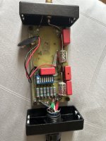
These dip switches are used to select the capacitors and resistors that form the amplifier's high-pass filter.How does the switching work? I assume that's why the battery is in there
I believe the purpose of the battery is to bias the two capacitors to "improve" the sound quality. Maybe @AVWERK can verify the circuit.
Regardless of it's effect on sound quality, what effect does a bias voltage have on a circuit like this?I believe the purpose of the battery is to bias the two capacitors to "improve" the sound quality.
It’s been 13 years since I made this and going on memory the battery was used to put a voltage on the shield like the Audioquest series of battery biased cables and was a real pain to implement
I believe JBL had something valid on keeping caps biased I recall ? but don’t hold me to it..
I did have one battery drain one time and could not tell it’s effect on the sound stage so building a set without the bias
would make it easier
I went off pics of an existing one for reference and hand drawn schematics. I will have to look around for it
DC bias is to improve the linearity of capacitor. JBL introduces DC bias with electrolytic capacitors in its crossovers. However, I don't know if film cap need DC bias to improve it linearity.Regardless of it's effect on sound quality, what effect does a bias voltage have on a circuit like this?
http://diyaudioprojects.com/mirror/members.aol.com/sbench102/caps.html
https://electronics.stackexchange.com/questions/292682/are-film-capacitors-affected-by-dc-bias
Based on the images, I come out with this schematic:
 — Scaled (31%).png")


For 50kΩ amplifier input impedance (NONE dip switch on), capacitance = 0.0302µF,
for 10kΩ to 33kΩ input impedance (dip switch #8 on) capacitance = 0.149µF,
for 5kΩ input impedance (7,8 dip switch on), capacitance = 0.224µF.
Can someone verify that the above schematic, components values and calculations are correct? Thanks.
Hello,My speakers are designed to be used with a 100 Hz first order high-pass filter. A pair of these RCA filters were included with the speakers: https://www.vandersteen.com/products/m5-hp
I want to design and build my own version of this filter, adding the ability to accept balanced and single-ended inputs/outputs, and maintaining the ability to adjust to match different amplifier input impedances.
The spec from the manual is a signal measuring 1v at the filter output at 1000 Hz should measure 0.707v at 100 Hz. The filter should be adjustable so that this attenuation can be achieved with a variety of amplifier input impedance values.
I know the basics of designing an RC filter, but I need help picking the resistance and capacitance values, and designing switchable loading.
If you only take in account the electrical part of the game to mathematically calculate components values for an optimal theoritical filter,
it probably won't match the acoustic speakers response (which is not a straight line) nor the real physical delay between the different speakers, and the result could be incertain.
Commercial brands usually use large anechoic rooms to do proprer measurtements,
that will be base for them to design filters that will be the best match to the speakers and their arrangement.
So, if you want a precise result you have to begin with raw speakers responses, and simulate what is possible with them or not.
If you want a good complementary acoustical filter without unwanted bump or dip,
prior to design it you have to make proprer raw speakers measurements - with a conserved time relationship between them -
that match the current speaker arrangement seen from the listening point.
Although at 100 Hz this will be difficult with in-room measurements because it is in hte range of the modal response of most domestic rooms.
If you don't have access to anechoic room, then the best next option is outdoor measurements, taking care of the 1st reflexion problem (ground)
Best,
Harold
Harold: The filter is supposed to be a first-order high-pass that is down -3dB at 100 Hz, or measures 0.707v at 100 Hz when, at the same level, a 1000 Hz tone measures 1.00v. Is matches a reversing filter in the amplifiers of the speakers subwoofers. No measurements are required.
@chrisng: Thank you so much! This is fantastic.
@chrisng: Thank you so much! This is fantastic.
Perfectly right ! Electrically speaking and making abstraction of all the others acoustical variables, I agreeSoaDMTGguy said:Harold: The filter is supposed to be a first-order high-pass that is down -3dB at 100 Hz, or measures 0.707v at 100 Hz when, at the same level, a 1000 Hz tone measures 1.00v.
Sorry ! I was mistaken by the title of the threadIs matches a reversing filter in the amplifiers of the speakers subwoofers. No measurements are required.
"Help me design a high-pass filter"
The only advice I could give was to achieve good acoustic measurements in order to design the "right" XO,
which has some chance to be different than the theoritical one.
This may not be a fantastic reply, maybe more realistic.
🙂
Best,
h.
Very nice build !👍Built my (SE) versions back in 2010 for my Quads and Vandy sub combo. No balanced versions alas..
View attachment 1227501
There would be nothing to gain technically from a passive balanced version imho.
Best,
h.
@SoaDMTGguy
Please check and post the component values in your M5-HP, especially the capacitor across the battery terminals.
Thanks
For the balanced version, just duplicate the capacitors, a 10MΩ resistor and 2 extra dip switches on the inverting phase and install a toggle switch to move the shunt resistor ground connection to it, this will allow the user to select a balanced or single ended connection.
Last edited:
At the very least I would pull the dip switch out and replace it (gold contacts)
He is soldering the battery in now and have seen coin cells being used and soldered in
on the latest versions
He is soldering the battery in now and have seen coin cells being used and soldered in
on the latest versions
It looks like those .033 Infinicap need to be replaced and the PCB needs to be thoroughly cleaned to avoid short circuits. If space permits, use a battery tray and leak-proof long-life lithium 9-volt batteries to prevent the same problem.
.png")
 9v Battery Holder 9 Volt Ba...png")
I have checked most of the capacitors and they are surprisingly still in spec. I am now replacing the switches. Hopefully this will solve the problem.
The area under the switches seems to be the worst affected by leak.
Can I also ask: there are 3 cables from the RCA jack: red - connected to the positive (point of RCA) and green and black that is connected to the ring of RCA. Black is connected to the negative line. Do I connect the green cable to the ground?
Thanks
Attachments

- Home
- Design & Build
- Electronic Design
- Help me design a high-pass filter to use with my Vandersteen Quatro speakers