I’m new on the forum but I’ve being working hard to understand this fascinating audio work.
I’m talking about Horn because the decision was already made for my PA but I’m asking for help regarding what drive should I choose my cabinet.
The target is: Lower frequency as possible with higher SPL considering the model available on the list at the final of the post.
Taking into account three very knew and well successful Low frequency horn designs
Doing reverse engineering comparing all those drivers the main Thiele/Small parameters they have in common are:
High VAS (> 440 L) and also high CMS once those two parameters are direct correlated.
Why high VAS is desirable? What is the negative effect of using low VAS on Low-frequency Horn?
Low QTS (< 2,9)
No doubt about QTS
High BL
No doubt about BL
Low Xmax (< 6mm)
Low Vd (< 0,725 L)
Here I see the first controversial parameter for Horn once usually high Xmax is desired for low frequencies cabinets and also high Vd, but looks like for Horn those variables are desired low to reduce throat pressure and as consequence reduce the distortion. Could someone confirm or explain?
My cabinet is a close of Electro Voice T18 but is not possible to buy the original T18’s drive DL18MT and change the design is not an option, so I’m looking for local driver to install on this cabinet and see what is the best tradeoff it can reach regarding low frequencies and SPL.
I’ve being also trying to study deeply the theory behind the Horn design but without time and experience with this product have been very hard to proper understand the things.
Some references I tried:
I also tried to simulate the T18 cabinet using Hornresp but the result is a little different from the original curve and maybe due to some simplifications, losses or wrong input data.
link for larger image: https://s9.postimg.org/70a5u5gwf/Horn_scheme.png
The throat was cute in sections like indicated below:
link for larger image: https://s18.postimg.org/k9kgdiaop/T18_Horn.png
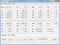
Hornresp input data
link for larger image: https://s15.postimg.org/mkegrxi23/Hornresp_input_data.png
The result from Hornresp @ 1W right?:
link for larger image: https://s12.postimg.org/xuy0arzf1/Hornresp_T18.png
Original Electro Voice response (Lower SPL @ 60 Hz and higher peak @ 150 Hz:
link for larger image: https://s18.postimg.org/jfh21xzax/T18_Original_SPL_response.png
The question I’m trying to answer is: What would be the best (Lower frequency as possible with higher SPL) and the worst drive option on the list bellow? why? Once I will not use T18 original drive what can I expected to loose and what can I expected to gain?
Note.: Unfortunately also JBL 2240 and Eminence Sigma Pro 18A2 are not available at my market
link for larger image: https://s22.postimg.org/xeqrff429/Subwoofer_availables.png
Thanks in advanced.
🙂
I’m talking about Horn because the decision was already made for my PA but I’m asking for help regarding what drive should I choose my cabinet.
The target is: Lower frequency as possible with higher SPL considering the model available on the list at the final of the post.
Taking into account three very knew and well successful Low frequency horn designs
o JBL 4818 (W-HORN) It uses JBL 2240 drive
o Cerwin Vega B36 (Earthquake) It uses Eminence Sigma Pro 18A2
o Electro Voice T18 It uses Electro Voice DL18MT
Doing reverse engineering comparing all those drivers the main Thiele/Small parameters they have in common are:
High VAS (> 440 L) and also high CMS once those two parameters are direct correlated.
Vas represents the volume of air that when compressed to one cubic meter exerts the same force as the compliance (Cms) of the suspension in a particular speaker.
Why high VAS is desirable? What is the negative effect of using low VAS on Low-frequency Horn?
Low QTS (< 2,9)
A unitless measurement, characterizing the combined electric and mechanical damping of the driver. In electronics, Q is the inverse of the damping ratio. The value of Qts is proportional to the energy stored, divided by the energy dissipated, and is defined at resonance (Fs).
No doubt about QTS
High BL
This is a measurement of the motor strength of a speaker. Think of this as how good a weightlifter the transducer is. A high BL figure indicates a very strong transducer that moves the cone with authority!
No doubt about BL
Low Xmax (< 6mm)
Short for Maximum Linear Excursion. Speaker output becomes non-linear when the voice coil begins to leave the magnetic gap. Although suspensions can create non-linearity in output, the point at which the number of turns in the gap (see BL) begins to decrease is when distortion starts to increase
Low Vd (< 0,725 L)
This parameter is the Peak Diaphragm Displacement Volume — in other words the volume of air the cone will move. It is calculated by multiplying Xmax (Voice Coil Overhang of the driver) by Sd (Surface area of the cone)
.Here I see the first controversial parameter for Horn once usually high Xmax is desired for low frequencies cabinets and also high Vd, but looks like for Horn those variables are desired low to reduce throat pressure and as consequence reduce the distortion. Could someone confirm or explain?
My cabinet is a close of Electro Voice T18 but is not possible to buy the original T18’s drive DL18MT and change the design is not an option, so I’m looking for local driver to install on this cabinet and see what is the best tradeoff it can reach regarding low frequencies and SPL.
I’ve being also trying to study deeply the theory behind the Horn design but without time and experience with this product have been very hard to proper understand the things.
Some references I tried:
- Low-frequency horn design using Thiele/Small driver parameters (1977) By D.B. Keele Jr
- On the Specification of Moving-Coil Driver for Low-Frequency Hon-Loaded Loudspeakers (1979) By W. Marshall Leach Jr
I also tried to simulate the T18 cabinet using Hornresp but the result is a little different from the original curve and maybe due to some simplifications, losses or wrong input data.
An externally hosted image should be here but it was not working when we last tested it.
link for larger image: https://s9.postimg.org/70a5u5gwf/Horn_scheme.png
The throat was cute in sections like indicated below:
An externally hosted image should be here but it was not working when we last tested it.
link for larger image: https://s18.postimg.org/k9kgdiaop/T18_Horn.png
Hornresp input data
An externally hosted image should be here but it was not working when we last tested it.
link for larger image: https://s15.postimg.org/mkegrxi23/Hornresp_input_data.png
The result from Hornresp @ 1W right?:
An externally hosted image should be here but it was not working when we last tested it.
link for larger image: https://s12.postimg.org/xuy0arzf1/Hornresp_T18.png
Original Electro Voice response (Lower SPL @ 60 Hz and higher peak @ 150 Hz:
An externally hosted image should be here but it was not working when we last tested it.
link for larger image: https://s18.postimg.org/jfh21xzax/T18_Original_SPL_response.png
The question I’m trying to answer is: What would be the best (Lower frequency as possible with higher SPL) and the worst drive option on the list bellow? why? Once I will not use T18 original drive what can I expected to loose and what can I expected to gain?
Note.: Unfortunately also JBL 2240 and Eminence Sigma Pro 18A2 are not available at my market
An externally hosted image should be here but it was not working when we last tested it.
link for larger image: https://s22.postimg.org/xeqrff429/Subwoofer_availables.png
Thanks in advanced.
🙂
Last edited:
Much better horn designs exist than the ones you mentioned. Unfortunately most of them are not commercial designs. luckily this is a diy forum so a lot of things have been tried and measured.
Your pictures are way too small to read but I can see that you simulated Nd and you should be using TH.
You can't pick the best driver by reading theory. You need to simulate all the drivers accurately and compare. You can't just pick and chose based on individual t/s parameters.
No matter what driver you chose you won't get it to play low frequencies, but it should go pretty loud.
Using this picture it should be easy to get a very accurate sim for your horn.
Notes:
Driver [VD]
the larger the better. Here there is no substitute for 'muscle'
Driver T/S Parameters and horn design are intimately related.
[Qts] of about 0.2 is a good place to be.
However, remember at the bottom end, the enclosure is probably no longer functionally a horn.
In a PA setting to go low and loud you must contemplate use of a horn array.
For a constant output, lower frequency means a lot larger.
For venues inside, the room acoustics dominate.
Placement is more important than size.
If room corners are available PWK has the answer.
Regards,
WHG
Thanks for some feedbacks.
I edited the original post adding link to see the picture from larger sources. Maybe as it was it put difficult on the understanding.
Thanks "just a gu"y for the 2D but i already have it, I also created the 3D and use it to get input dat for the hornresp software for simulations. You can also see the picture.
I'm doing a lot of simulations, for all drives i shared with you and i will post the results.
Anyway experience create shot-cuts, so i could save some time.
For any reason the drives i highlight have a lot in common and for any reason the engineer chosen that T/S parameter in common for the Horn.
Your sim needs to be TH, not Nd.
You should change 4 pi to 2 pi.
You should change all segments to PAR, not CON.
EV makes drivers so the horn was very likely designed around the driver. You are trying to do the opposite, find a driver that works in the horn. So you need to simulate all the potential candidates and let the sim tell you what works best. You need to start with an accurate sim.
If you can get B&C I would try those, they are probably cheaper and better than some or maybe all the options you are considering.
hello "just a guy"
Thanks again for you support i will try to implement all your suggestion. I also finished all 15 simulatiosn yesterday but i'm processing the data before post the results. Maybe i will need to simulate all again due to your suggestions but could you explain a little more your proposals?
Why change horn type from Conical to Parabolic once all segments are conical?
change 4 pi to 2 pi i can do it, are you sure they considered floor effect on the semi anecoic chamber to measure the response?
The ND refer to the number of drivers, or are you refering to different ND? where i find this variable to change it to TH?
thanks for your support 😀
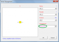
Nd is the driver arrangement, nd is normal driver th is tapped horn. Double click on the letters nd to bring up a dialog box. Subwoofers are virtually never suspended so it is accurate to model in 2pi.
Why change horn type from Conical to Parabolic once all segments are conical?
The segments are not conical, if they were I wouldn't tell you to change to PAR. When you have 2 parallel sides in your enclosure you are dealing with parabolic, not conical. If no sides were parallel and all 4 walls expanded in cross sectional area (like a cone) then you would use CON. But that's not the case, your box has 2 parallel sides and the segment are all PAR.
change 4 pi to 2 pi i can do it, are you sure they considered floor effect on the semi anecoic chamber to measure the response?
I have no idea how they measured. Why do you assume it was in an anechoic chamber? Most people and companies measure in 2 pi. Most simulators only simulate 2 pi. 2 pi is the standard.
The ND refer to the number of drivers, or are you refering to different ND? where i find this variable to change it to TH?
thanks for your support 😀
As saba said, click the Nd text and it will change. Keep clicking it until it changes to TH.
The box beside Nd is for the number of drivers. Nd itself is for the loading arrangement (Nd is end loaded, TH is for tapped horn).
I assume Nd used to stand for number of drivers back when there were no other options in Hornresp but now there are many other options so you should probably consider Nd as meaning end loaded in current versions of Hornresp and use the box beside the text to describe the number and arrangement of the drivers.
Thanks again for all feedback.
Changes done.
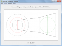
take a look at the schematic and the new out put using the original driver. Comparing with the original output we still see high difference but maybe is enough just to compare drivers.
link for larger image: https://s22.postimg.org/jl55yycwx/Hornresp_Schematic.png
Link for larger image: https://s15.postimg.org/unuexzjmj/Hornresp_T18_correted.png
Link for larger image https://s14.postimg.org/y1z4zr7kh/T18_Original_SPL_response.png
Link for larfer image: https://s14.postimg.org/y1z4zr7kh/T18_Original_SPL_response.png
Original output initiate from 25Hz / Simulation from 20Hz
Original output present inflexion @ 50-60Hz / Simulation present a peak
Original output present 100 dB @ 100Hz / Simulation too 🙂
Original output max peak 110 dB @ 150Hz / Simulation max peak 107 dB @ 180Hz
The simulation for all those 15 drives were done but i will redo all.
Changes done.
take a look at the schematic and the new out put using the original driver. Comparing with the original output we still see high difference but maybe is enough just to compare drivers.
An externally hosted image should be here but it was not working when we last tested it.
link for larger image: https://s22.postimg.org/jl55yycwx/Hornresp_Schematic.png
An externally hosted image should be here but it was not working when we last tested it.
Link for larger image: https://s15.postimg.org/unuexzjmj/Hornresp_T18_correted.png
An externally hosted image should be here but it was not working when we last tested it.
Link for larger image https://s14.postimg.org/y1z4zr7kh/T18_Original_SPL_response.png
Link for larfer image: https://s14.postimg.org/y1z4zr7kh/T18_Original_SPL_response.png
Original output initiate from 25Hz / Simulation from 20Hz
Original output present inflexion @ 50-60Hz / Simulation present a peak
Original output present 100 dB @ 100Hz / Simulation too 🙂
Original output max peak 110 dB @ 150Hz / Simulation max peak 107 dB @ 180Hz
The simulation for all those 15 drives were done but i will redo all.
An externally hosted image should be here but it was not working when we last tested it.
Your sim is still not accurate, you can see just by looking at your Hornresp schematic that the driver isn't in the right spot. The driver should be in the middle of the last segment, and the edge of the driver should be just a couple of cm away from the horn mouth.
Look at this picture, S4 needs to be where the red line is drawn. You will need to change things up a bit to make this happen, maybe combine the first two segments so you have an extra segment to use at the end of the horn.
Look at this picture, S4 needs to be where the red line is drawn. You will need to change things up a bit to make this happen, maybe combine the first two segments so you have an extra segment to use at the end of the horn.
An externally hosted image should be here but it was not working when we last tested it.
Actually, the throat chamber is entering the flare at S2, which is also wrong. I don't think there's anything you can do about that except "waste" the first segment making it as short as possible.
That eats up S1 and S2 just to start the horn flare, and S4 and S5 are the area between the red line in the picture I showed and the horn mouth. That only leaves S3 free. It's hard to say where the best spot to put S3 would be, I'd draw the horn out as a straight horn and that should make it clear where S3 should be. Probably at the start or end of the last bend in the flare.
Unfortunately there's not enough segments in Hornresp to sim this very accurately, you could start with Hornresp and export to Akabak and add a few more segments if you wanted to get a more accurate sim.
If I had to sim this horn, this is probably where I would put the segment markers. S1 and S2 would be the same cross sectional area and in the same place and that segment would have a length of 0.01 cm. That puts the throat chamber firing into the beginning of the horn flare (which has to be S2).
S3 could be either at the beginning or the end of the last bend as shown by the two blue lines. Pick one or the other.
S4 has to be where the red line is. There's no way around that or the driver won't be in the right place.
S5 has to be the horn mouth.
Unfortunately there's not enough segments to get more detailed than that.
An externally hosted image should be here but it was not working when we last tested it.
Hi all
Here are the results
Link for larger image: https://s16.postimg.org/3ou8k1g85/Hornres_all_spl.png
Link for larger image: https://s16.postimg.org/k1h1v8mxh/Hornres_all_spl_40_110.png
Link for large image: https://s11.postimg.org/bk2s19u4z/Hornres_all_spl_40_80.png
Taking into account the SPL mean from two different badwidth the simulations highlight some good drivers presenting better results them the original one.
They are (the list represent just simulation order and not rank)
Snake ESX185
JBL 18SW1
Snake HPX2180
SPL 18SG12
SPL 18SG16
Oversound 18-800-ST
Oversound SUB-1000
The Snake HPX2180 would be the winner and the Oversound SUB-1000 as the 2nd place them the Snake ESX185 as 3rd.
https://s15.postimg.org/5yu915yrf/Hornres_best_cases_SPL.png
The doubt is just about the simulation errors, i mean the result is a little different from the original SPL curse in terms of shape.
Here are the results
An externally hosted image should be here but it was not working when we last tested it.
Link for larger image: https://s16.postimg.org/3ou8k1g85/Hornres_all_spl.png
An externally hosted image should be here but it was not working when we last tested it.
Link for larger image: https://s16.postimg.org/k1h1v8mxh/Hornres_all_spl_40_110.png
An externally hosted image should be here but it was not working when we last tested it.
Link for large image: https://s11.postimg.org/bk2s19u4z/Hornres_all_spl_40_80.png
Taking into account the SPL mean from two different badwidth the simulations highlight some good drivers presenting better results them the original one.
They are (the list represent just simulation order and not rank)
Snake ESX185
JBL 18SW1
Snake HPX2180
SPL 18SG12
SPL 18SG16
Oversound 18-800-ST
Oversound SUB-1000
The Snake HPX2180 would be the winner and the Oversound SUB-1000 as the 2nd place them the Snake ESX185 as 3rd.
An externally hosted image should be here but it was not working when we last tested it.
https://s15.postimg.org/5yu915yrf/Hornres_best_cases_SPL.png
The doubt is just about the simulation errors, i mean the result is a little different from the original SPL curse in terms of shape.
Hello "just a guy"
I tryed three differents schemas and that one was the closest as possible to reach the original T18 output but in that time looks like my segments were wrong as you highlighted so tomorrow i will try to check it again.
For sure if we find different set up i can run simulation to compare and discover what is more accurated.
Even if the results were not well accurate i think the error would be the same for all drivers so maybe the differences between them would not change too much.
I assume Nd used to stand for number of drivers back when there were no other options in Hornresp
Hi just a guy,
Your assumption is correct.
Nd now stands for "normal driver arrangement" (normal as in standard or default).
Kind regards,
David
Attachments
Hello David,
Thanks to visit this thread.
"Just a guy" suggests me to change the sections and the lenghts to improve the simulation accuracy.
What sections would you suggest to use in order to have more accuracy using Hornres?
Thanks to visit this thread.
"Just a guy" suggests me to change the sections and the lenghts to improve the simulation accuracy.
What sections would you suggest to use in order to have more accuracy using Hornres?
Hi LORDSANSUI,
JAG has it correct, used the "rear" chamber as a horn throat chamber, and set L12=0.01, etc... (see JAG's drawing in Post #13).
You can draw a development of the horn path (roll-out), e.g.: see Post #1 here:
http://www.diyaudio.com/forums/subwoofers/190635-th-18-flat-35hz-xoc1s-design.html
That might help in defining the optimum S3 and S4 positions, but I doubt it will make much difference.
Another interesting source are all the threads on Cubo subs, which have a similar form/path.
Regards,
Another interesting source are all the threads on Cubo subs, which have a similar form/path.
This...
Hello David,
Thanks to visit this thread.
"Just a guy" suggests me to change the sections and the lenghts to improve the simulation accuracy.
What sections would you suggest to use in order to have more accuracy using Hornres?
Hi Marcelo,
Because Hornresp is limited to four segments, any simulation model can only be an approximation. The specification of the model is very much a judgement call on the part of the user, and is dependent upon the simplifying assumptions made. The attached arrangement could be one possibility, perhaps?
Kind regards,
David
Attachments
- Home
- Loudspeakers
- Subwoofers
- Help - Low frequency horn – T18