I'm looking at a Leak Trough Line 3 (mono) and a GATE (glass audio tube engineering) stereo decoder for a friend.
Basically one channel is twice the volume of the other.. there are two pots inside, one labeled LEVEL (volume) .. the other smaller FREQ (which I assumed was the separation pot but doesn't seem to make any difference to anything ?! I've returned it to its original position) any ideas??? ...
Basically one channel is twice the volume of the other.. there are two pots inside, one labeled LEVEL (volume) .. the other smaller FREQ (which I assumed was the separation pot but doesn't seem to make any difference to anything ?! I've returned it to its original position) any ideas??? ...
Is that one of the 'valve' decoders which actually uses an ordinary decoder chip to produce stereo, which then gets buffered (and possibly matrixed) by some valves?
OK. I just thought that 'glass audio tube engineering' might vaguely imply the presence of a vacuum device?
well they were producing a stereo decoder for the Leak Trough Line valve tuner … and 'glass audio tube engineering' gave them a cute acronym of G.A.T.E …
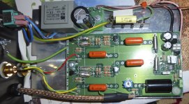
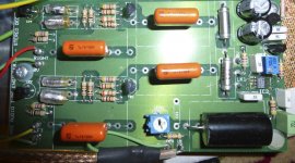
There are 4 caps/resistors/somethings (2 on each channel) which are plastic with an outer layer of foil (against interference?) which look almost custom (maybe just the foil).. when I measure resistance across them they have very different measurements: by a factor of 10!! but I could be measuring resistance of the rest of the circuit? and the difference shows a failed component somewhere else in the circuit???
There are 4 caps/resistors/somethings (2 on each channel) which are plastic with an outer layer of foil (against interference?) which look almost custom (maybe just the foil).. when I measure resistance across them they have very different measurements: by a factor of 10!! but I could be measuring resistance of the rest of the circuit? and the difference shows a failed component somewhere else in the circuit???
these things are clear plastic with a thin layer of foil.. sausage roll style…. sound familiar to anyone?
They sound like Polystyrene capacitors. Very hard to beat for sound quality, but they are sensitive to heat (soldering iron). Replace with the same types.
When I do a rebuild in stereo decoder sections, its normal to have to replace the resistors due to drifting values. Sometimes you may find capacitors that have seen better days. I try to match those components since this is the matrix. The diodes are also something I match for voltage drop in discrete systems.
-Chris
Yes, the description sounds like polystyrene caps. Generally reliable, unless ruined by excess heat from poor soldering technique. Unlikely to be causing the symptom you have, but there is always a first time for everything.
You need a circuit diagram. If you can't obtain one then you will need to draw it out from the circuit. Alternatively, if you can identify the chip they used then it is a fairly safe bet that the circuit won't be much different from what is given in the chip datasheet.
By the way, the FREQ pot probably adjusts the free-running frequency of the oscillator in the PLL so that it is near a multiple of the 19kHz pilot tone. Probably 76kHz, but could be 38kHz.
Hi koyaanisqatsi,
To set the frequency, you might have to provide a signal without the 19 KHz pilot so the oscillator runs in free running mode. From there you can set it up to the frequency it needs to be at. This will affect FM stations that are coming in a bit weaker, allowing a more stable stereo lock. It's a worthwhile adjustment to do. It's going to be close to the proper frequency as DF96 mentioned. So, your choices are: 19, 38 or 76 KHz. You will most often see 76 KHz, or 19 KHz. Looking at a 38 KHz signal was more popular with the tube MPX decoders where phase also comes into play. Don't be too surprised if the test point is 38 KHz either. The stereo separation control is the phase adjustment, for that you need to be able to feed it an MPX composite signal using test tones. You measure one channel, then switch channels on the MPX generator and adjust for the minimum signal. Find a balance between the two channels.
I guess that without said generator, you could make a best attempt adjustment by taking an FM program and adjusting this control for the widest stereo image. I don't recommend you do this, but you may have no choice. If you have the option of using an FM multiplex signal, either composite or RF in the band, then use the generator!
You may also have some traps on each channels output. One kills 19 KHz from leaking out, the other targets 38 KHz leakage. They should only require a small tweak at most unless someone has been in there. Please don't fail to do this. Both signals will exist if you feed in a 19 KHz signal, or from your FM stereo (MPX) generator with the normal audio muted, just the 19 KHz pilot tone active. The generator approach is better since they normally use a 19 KHz crystal - so they are more accurate than the average sine wave oscillator. A good digital signal generator would be fine, like an HP 3324A, 3325A/B or 3336A/B. Any newer HP/Agilent/Keysight or similar equipment should be fine for this. Some of the Chinese Ebay DDS generators may also be useful (check-'em first with a good frequency counter!).
-Chris
yes.. they look the same as the polystyrene caps on ebay … can I test them in situ? or would I need to demount them? I'm basically just comparing like for like in each channel ..
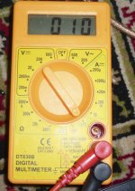
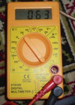
the smaller of the two polystyrene caps in each channel measure 010 and 063 respectively … the larger ones measure 038 and 042…
am I measuring anything worthwhile ? 😕
the smaller of the two polystyrene caps in each channel measure 010 and 063 respectively … the larger ones measure 038 and 042…
am I measuring anything worthwhile ? 😕
Attachments
Hi koyaanisqatsi,
No, you aren't measuring anything useful. Those silver capacitors are polystyrene for certain. The orange ones could be polypropylene - maybe.
To get a good read on any component, it must be removed from the circuit. Tube circuits are a little different sometimes. When a tube isn't powered, it is a very small capacitor. No conductivity. So you just have to worry about other components in that direct circuit. With solid state, this assumption is no longer true.
To measure capacitance in any circuit, you want to at least lift one end to measure. That cuts down on the strays or any other funny behavior that could swamp out your results. Your meter does not appear to measure capacitance anyway. Not in any form I've seen with the DT-830 model. It appears to be set for hFE measurements.
Keep in mind that your type of meter is "approximate". It would be better if it were a needle type display to remind you that the readings are not that accurate. That's the trouble with digital meters, you tend to think they are a lot more accurate than they are in reality. I'll grant you that you're probably better than the standard 2% accuracy of a pointer type meter, but if you work out the accuracy for your reading, you might be depressed. Better meters = better readings.
-Chris
Hi DF96,
Well, that explains a lot. First stop: the data sheet for that chip (as you suggested earlier).
-Chris
Well, that explains a lot. First stop: the data sheet for that chip (as you suggested earlier).
-Chris
Hi koyaanisqatsi,
No, not at all. It's just that a chip means the basic circuit is a "canned" package that is difficult to deviate from. Perusing the data sheet should give you a lot of insight as to how it works and how to set it up. Application notes are your best friend in the service industry!
I can also second the comment that DF96 made about commercial products often being very close to the published application circuit. When Dolby Prologic came out, many circuits were a big secret. In my Analog Devices manual, there they were laid bare for all to see. In this particular case, the Canadian Distributor couldn't get the details from the manufacturer. So I copied the section and sent it to them (I was authorized warranty). Let's just say they were both amazed and grateful for this information. I imagine the manufacturer might not have been amused at the time. I had the same book that they did. 🙂
Anyway, download the data sheet and go over that first. You may also be able to find an application note (separate publication) that showcases that chip. Another good resource are manuals for other brands that use the same chip. Just scan for tuners from the same general time period for that IC. Many will include the alignment instructions (being a service manual).
One question for you. Do you have access to an FM stereo generator or MPX generator? Many FM stereo generators also have an MPX output. That allows you to test only the MPX decoder (stereo decoder).
-Chris
Interesting that the TDA7040 datasheet describes it as being low voltage (tyically 3V supply) and intended "for low cost FM stereo radios". It is amazing how many cheap and cheerful radio chips end up in 'high end' audio! THD 0.3%, noise -70dB, channel separation 40dB. The separation is OK, but the noise and THD would degrade a high quality FM tuner.
Hi DF96,
Yeah ... I was really hoping he would have something better in there. I'm not familiar with the TDA products.
Your assessment is, unfortunately, bang on. Maybe he could sneak in a better MPX chip and tell the owner the original had a problem he couldn't fix? Would the power supply in the box support a higher voltage through modification?
The 3V supply really points to the intended use as a portable radio.
-Chris
Yeah ... I was really hoping he would have something better in there. I'm not familiar with the TDA products.
Your assessment is, unfortunately, bang on. Maybe he could sneak in a better MPX chip and tell the owner the original had a problem he couldn't fix?
Would the power supply in the box support a higher voltage through modification?The 3V supply really points to the intended use as a portable radio.
-Chris
I like the sound of a better MPX chip … the transformer in there is 2x9v so should be able to use one of those.
This GATE decoder got rave reviews from David Price/Hi-FiWorld magazine 25 years ago, with a cheap MPX chip and al'
would another MPX chip need any other changes to the circuit other than a higher voltage?
but back to the main fault… if you were to take a guess, what are the most likely component/s to have failed or drifted away from spec? (that is which component/s should I checking first?)… resistors? should I just replace all the resistors anyway? as the decoder is at least 20 years old already: as I'm going to have to lift them off the circuit board to test them.
thanks for you're help by the way, you've been a wealth of information already…
Last edited:
Hi koyaanisqatsi,
It's a surface mount chip by the looks of it. You would very probably need a completely new board to use any other chip. The one other option would be to look at the entire lineup of stereo demodulator chips from that manufacturer. See if there is a higher performance one with the same pin-out. It's a long shot, but worth trying.
To say anything further on this I'd have to have a good look at the spec sheet. You are probably stuck with using a different IC. On the plus side, you have your pick of later, much better MPX chips. Some may even have complete plans for construction. You might also find a complete multiplex design using current parts on Ebay that you could buy, adjust the power supply, and install.
-Chris
- Status
- Not open for further replies.
- Home
- Source & Line
- Analogue Source
- Help! LEAK Trough Line GATE decoder problem