Hi,
I have a HT supply to a pair (one in each channel) of 6c45 valves. I took some photos of the circuit that filters the B+ as I think the hum could be quieter, however I did not take any measurements as I thought I would be able to just work it out......but sadly my brain is not large enough to achieve this :-(
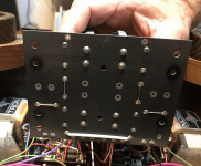
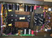
What I am very confused with is the large value of the resistors that seem to be used as part of the RC smoothing filter that I assumed was the configuration. The caps are 220uF and the resistors look like 470K?!?
I clearly need to go back and measure things, but alas the amplifier in question is absurdly heavy and on a re-enforced shelf that to take down safely requires 2 people (one of which is not my wife) - so is by appointment rather than by choice.
Any ideas on what is going on with the circuit - I thought it would be simple to see.
I have a HT supply to a pair (one in each channel) of 6c45 valves. I took some photos of the circuit that filters the B+ as I think the hum could be quieter, however I did not take any measurements as I thought I would be able to just work it out......but sadly my brain is not large enough to achieve this :-(
What I am very confused with is the large value of the resistors that seem to be used as part of the RC smoothing filter that I assumed was the configuration. The caps are 220uF and the resistors look like 470K?!?
I clearly need to go back and measure things, but alas the amplifier in question is absurdly heavy and on a re-enforced shelf that to take down safely requires 2 people (one of which is not my wife) - so is by appointment rather than by choice.
Any ideas on what is going on with the circuit - I thought it would be simple to see.
Attachments
I would guess, (no schematic) that the 470k resistors are bleeder resistors to drain the capacitors when power is turned off. They could also be equalizing resistors if the pairs of capacitors are in series.
Those are in parallel with the capacitors, not in series. They just drain a small amount of current.
The resistors at the base of each capacitor are across the capacitors. You can see this from the traces shown in your first picture. There is not enough detail to show whether these are simple bleeders or if the capacitors are stacked to handle higher voltage. A more complete schematic is required to assess the power supply filter function.
Thanks everyone! This is great.
Unfortunately I don't have a schematic, and the guy who built it for me is super secretive about his designs so he will never share :-(
I designed it as an Ongaku copy in 1997 and it ended up as a Frankenstein of my parts and chassis and his design and more parts....as I ran out of time and talent during my dry build.
The hum is 120 Hz, it's not huge but it could be better.
I THINK (by logic only) the supply comes from a valve rectified DC that supplies the 211 power valves at 1000V, through a voltage doubler. What's not clear to me is how this is stepped down and smoothed (although I am already a little clearer now thanks!) to provide the B+ at 138V on the 6c45 valves.
The 6c45 valves are interstate through Lundahl 1660 transformers into the 211.
I can't see any other taps from the PS transformer or diodes to supply this independently, only other diodes are for the DC heaters for the 211 valves.
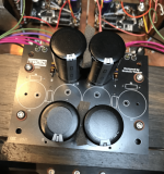
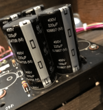
See images attached. It looks like the 211 valve filtering is also via similar banks of 400V caps in series too, again probably with bleeder resistors at what looks like 910K
The first filtering comes from a Pi filter with Lundahl LL1673 10H chokes I can see hidden at the back of the PS transformer
Thanks so much 😎
Unfortunately I don't have a schematic, and the guy who built it for me is super secretive about his designs so he will never share :-(
I designed it as an Ongaku copy in 1997 and it ended up as a Frankenstein of my parts and chassis and his design and more parts....as I ran out of time and talent during my dry build.
The hum is 120 Hz, it's not huge but it could be better.
I THINK (by logic only) the supply comes from a valve rectified DC that supplies the 211 power valves at 1000V, through a voltage doubler. What's not clear to me is how this is stepped down and smoothed (although I am already a little clearer now thanks!) to provide the B+ at 138V on the 6c45 valves.
The 6c45 valves are interstate through Lundahl 1660 transformers into the 211.
I can't see any other taps from the PS transformer or diodes to supply this independently, only other diodes are for the DC heaters for the 211 valves.
See images attached. It looks like the 211 valve filtering is also via similar banks of 400V caps in series too, again probably with bleeder resistors at what looks like 910K
The first filtering comes from a Pi filter with Lundahl LL1673 10H chokes I can see hidden at the back of the PS transformer
Thanks so much 😎
Attachments

Excuse me? How wrong is this?Unfortunately I don't have a schematic, and the guy who built it for me is super secretive about his designs so he will never share :-(
An actual schematic can be drawn out by any sufficiently motivated observer. What does this mysterious guy who built it expect to gain by making your life more difficult? And, "his designs" is an affectation. What a dweeb.
Sorry to get up on a soapbox, but this vein of valve audio just chaps my butt.
All good fortune,
Chris

Yeah I know, but his position is to also want to protect me from dangerous voltages I think, and of course there is a sense that i would not be able to improve or otherwise make changes that are advantageous I suppose.Excuse me? How wrong is this?
An actual schematic can be drawn out by any sufficiently motivated observer. What does this mysterious guy who built it expect to gain by making your life more difficult? And, "his designs" is an affectation. What a dweeb.
Sorry to get up on a soapbox, but this vein of valve audio just chaps my butt.
All good fortune,
Chris
And regarding the "motivated observer"; you probably need to add the word knowledgable or competent in there as I am motivated and still don't know it other than thematically!!!
So I have another question on my amplifier as I try and grow understanding of it as a motivated uneducated observer 🙂
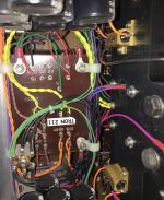
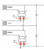
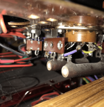
I have a voltage doubler from a 450V tap on my power supply transformer. I am tracing the circuit as much as I can, and it seems like there are four large 100R ohmite resistors as shown, any idea why? - I know there is a 100R earth lift on the amplifier, but not sure if this is part of that approach. any ideas? Thanks so much for the continued support
I have a voltage doubler from a 450V tap on my power supply transformer. I am tracing the circuit as much as I can, and it seems like there are four large 100R ohmite resistors as shown, any idea why? - I know there is a 100R earth lift on the amplifier, but not sure if this is part of that approach. any ideas? Thanks so much for the continued support
Attachments
Simple answer:
Valve (tube) rectifiers have a specified 'anode (plate) supply resistance', if the HT secondary winding resistance is less than the spec, then it is normal to add resistors to each anode. Good practice anyway.
If the winding resistance is too low you will likely get the dreaded flashover as the rectifier warms and starts to pass current to 'empty' reservoir caps. The resistors help reduce the initial current until the caps are charged.
In your doubler configuration they also help load share the slight differences in anode current if there is a small mis-match in the 5U4.
Are you wanting to make changes to the layout or circuitry, if you knew they had some benefit and you were competant enough?
Do you have measurement equipment that can be used to diagnose issues like hum?
Do you have measurement equipment that can be used to diagnose issues like hum?
Thanks so much for this, I am learning all the time.Simple answer:
Valve (tube) rectifiers have a specified 'anode (plate) supply resistance', if the HT secondary winding resistance is less than the spec, then it is normal to add resistors to each anode. Good practice anyway.
If the winding resistance is too low you will likely get the dreaded flashover as the rectifier warms and starts to pass current to 'empty' reservoir caps. The resistors help reduce the initial current until the caps are charged.
In your doubler configuration they also help load share the slight differences in anode current if there is a small mis-match in the 5U4.
I have a probe via the REW software and a laptop to measure hum and have used this on my preamp. I have replaced components to rebuild things, and I am an engineer and designer BUT I am not an electronics expert, and I do respect the risks with 1000VAre you wanting to make changes to the layout or circuitry, if you knew they had some benefit and you were competant enough?
Do you have measurement equipment that can be used to diagnose issues like hum?
All I want to do in the beginning is to UNDERSTAND what the circuit is and to then hypothesise where I might have the opportunity to change things, if at all. The next time I move the amplifier I will do some measurements. I am less keen on looking at the 1000V side. I already understand the 211 heater side which is 10.5V AC full wave rectified and then 47000uF to ground, series 0.82R, then another 47000uF to ground to provide 10V DC.
I wanted to see how the B+ came from to feed the driver valves The main voltage doubled power supply is complicated to work out due to visual access has 5 chokes and on and 16 capacitors in banks that are likely used solely for the 211 B+ but as yet I am not sure. I wanted to see if the driver valve had the same attention and to understand it.
Before you make any measurements, you should reverse engineer the schematic.
That will make any further work much safer. It just isn't that hard.
That will make any further work much safer. It just isn't that hard.
good advice, I am slowly working on it!Before you make any measurements, you should reverse engineer the schematic.
That will make any further work much safer. It just isn't that hard.
And make sure that your probes are rated higher than the highest voltages present in the amplifier.
The parallel resistor is a bleeder resistor.
Its meant to drain power after power down to make amp more safe to work on.
I tend to use a low power LED and resistor in series for a visual indication of safety.
Its meant to drain power after power down to make amp more safe to work on.
I tend to use a low power LED and resistor in series for a visual indication of safety.
yeah I have probes thatAnd make sure that your probes are rated higher than the highest voltages present in the amplifier.
Thanks everyone, I am not in a hurry just gradually moving my knowledge forward 🙂The parallel resistor is a bleeder resistor.
Its meant to drain power after power down to make amp more safe to work on.
I tend to use a low power LED and resistor in series for a visual indication of safety.
- Home
- Amplifiers
- Tubes / Valves
- Help in understanding PS Filtering