I suppose, those days design consideration was quality and long lasting product as their product was new/ one of its kind, unlike today where products are desined with lifespan for recurring revenue source.OMG, thanks for that. Some of the older equipment has quality beyond our memory.
Syllabus changed 🤓Funny that 80 years ago they knew how to make attenuators and now they don’t..,,
Wow love those picks of old school attenuators. They look like they were built to last a lifetime. Quality.
in post #39+40 under
https://www.diyaudio.com/community/...od-or-not-for-hi-fi.60548/page-2#post-7375185
I ask for a replacement for a P&G potentiometer by a stepped attenuator (e. g. ELMA type 04)
The actually question is, what resistor type should I prefer ?
https://www.diyaudio.com/community/...od-or-not-for-hi-fi.60548/page-2#post-7375185
I ask for a replacement for a P&G potentiometer by a stepped attenuator (e. g. ELMA type 04)
The actually question is, what resistor type should I prefer ?
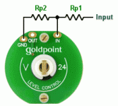
Question - if using a shunt potentiometer at the input of a valve stage, does the shunt part need to be the same as the series resistor?
So if we choose a 47K series resistor, what would be the consequences of using 47K, 100K or 250K for the shunt value?
So if we choose a 47K series resistor, what would be the consequences of using 47K, 100K or 250K for the shunt value?
Update:
Some time doing research seems to suggest that series resistor should be half of shunt. Also series resistor as low as possible, like 33K or less for input to a valve stage. Ideally much less. Found some comments:
A reasonable load for any normal line driving stage is:
Most can cope with driving 10k to 100k.
Some will cope with driving 2k to 10k.
Very few will be able to drive less than 2k, but some op-amps can.
34k input resistor value is a bit high. I like to do 50~70% pot value for input resistor value so loudness at 12 o'clock is about the same as a normal pot. Also did the Shunt mod today on my 50k pot tested with 25k and 47k, and 33k has a better control of the volume.
91k to 191k for a 100k pot, 47k to 97k for a 50k pot, 18k to 38k for a 20k pot. I'd recommend going Vishay Z foil VAR (thru hole), VSM (surface mount). It will be well worth the extra.
I want to ask about a quite different design approach based on the fact that most modern amps have gain settings (mine has 4).
So instead of the full range attenuation you set the amp to the lowest gain and design a stepped attenuator from very low to the volume level you need 90% of the time. When you occasionally need higher volume just change the gain. I think this can potentially improve the sound quality and any imperfections inserted by the volume control to the minimum.
Do you have an opinion on this approach?
In particular, I have 75 Ohm DAC output and 10 kilohm power amp input. I think this is very typical for many people here. What would be the potentiometer value if I need only a narrow range of attenuation? I can certainly add some fixed resistors in line and in Lpad to narrow the potentiometer requirements.
I think that this is an excellent observation and can go a step further by using those special high dollar resistors in the places where they will get used. I am not sure how/where the gain setting is placed in the circuit. I thought that it was at the input but that approach doesn't really change the gain of the circuit, it just reduces the signal voltage. I am interested in knowing more because I have a similar situation that I want to sort out. Seems that many of the preamps that I build have too much gain and I end up with a voltage divider at the input.
@Ixnay in my power amp the actual gain is fixed and the selector controls the input buffer. From the amp doc:
"By default the Purifi module applies a gain of 12.8dB to the signal. The BUFFER jumpers in position 2/3 activate the operational amplifiers and add + 7.2dB of gain to the signal. The active Gain + jumper brings the total gain to 25.3dB and the maximum power of the module is reached with a source signal of ~ 2.25V RMS."
From the Bifrost doc about output: "Maximum Output: 2.0V RMS single-ended, 4.0V RMS balanced. Output Impedance: 75 ohms for both [rca or balanced]".
Right now I'm running the 2nd lowest gain and the volume dial is at 9 am - it's that much of power.
Yup, that is where volume control is right now too. I will likely have to drop 25DB to get things where I want. Now the question is, will that push the preamp tube too right up to get the volume but not have too much distortion. We'll see. Seems that my B1K has about 17.8 DB gain.
- Home
- Source & Line
- Analog Line Level
- Help in choosing a potentiometer as a "Passive preamplifier"

