Looks like A-X1 for 200V input A-X2 for 220V and A-X3 240V.
a-x the output, for a not stabilised supply of 24V= that is 18V~
And if there was a stabilisation circuit then round 24V~
To get 5A DC the transformer is capable of allmost 8A~
No garanty I am right !
Mona
a-x the output, for a not stabilised supply of 24V= that is 18V~
And if there was a stabilisation circuit then round 24V~
To get 5A DC the transformer is capable of allmost 8A~
No garanty I am right !
Mona
I found my other multimeter that is a lot more accurate than the one I used earlier. Here are the new readings:
Left side of the transformer:
x - a 0.3R
Right side of the transformer:
A - X1 = 8.6R
A - X2 = 9.6R
A - X3 = 10.7R
X1 - X2 = 1.4R
X1 - X3 = 2.3R
X2 - X3 = 1.3R
I hope these readings make more sense.
K
Left side of the transformer:
x - a 0.3R
Right side of the transformer:
A - X1 = 8.6R
A - X2 = 9.6R
A - X3 = 10.7R
X1 - X2 = 1.4R
X1 - X3 = 2.3R
X2 - X3 = 1.3R
I hope these readings make more sense.
K
What is the probe to probe resistance measurement?
You need to correct your winding measurements by subtracting the probe to probe reading.
This new set shows a probe to probe "zero" reading of ~0r3.
Check that and adjust your winding measurements.
Your new readings confirm the tapping order given by the first set.
A - X1 - X2 - X3
Since these are very much higher than x -a, this indicates that A - Xy is the high voltage side and a-x is the low voltage side.
Use your Mains Bulb Tester to power ON the transformer assuming that A - X3 is the primary.
You can then measure the input voltage (careful it's mains voltage) and the output voltage.
You can also measure the A - X1 and A - X2 voltages while powering the A - X3 tappings. As a check you can measure X1 - X2 voltage and X2 - X3 voltage. These are still mains voltage and LIVE, be careful.
Last edited:
I didn´t check the probe to probe resistance in a hurry, but I´ll go through that later today.
I´m glad the puzzle is starting to unfold. Thanks for the help so far!
I´m glad the puzzle is starting to unfold. Thanks for the help so far!
Let me do a summary of the last findings:
m - shield
a/x - secondary
A - X1 - X2 -X3 - multi-tapped primary
The primary consists of 3 coils connected in series A-X1, X1-X2, X2-X3.
So your resistance measurements should match the equations (A-X3)=(A-X1)+(X1-X2)+(X2-X3) , (X1-X3)=(X1-X2)+(X2-X3) ,................and so on.
I assume this PSU was used for relay/contactor control circuits in an industrial environment. On the empty heatsink a bridge rectifier was probably mounted.
You can expect an off-load voltage on the secondary of about 22-24Vrms, but I wouldn´t guarantee.
Last edited:
Let me do a summary of the last findings:
m - shield
a/x - secondary
A - X1 - X2 -X3 - multi-tapped primary
I assume this PSU was used for relay/contactor control circuits in an industrial environment. On the empty heatsink a bridge rectifier was probably mounted.
You can expect an off-load voltage on the secondary of about 22-24Vrms, but I wouldn´t guarantee.
This was my conclusion of the use of this transformer also. Maybe industrial robotics of some sort.
I just got the transformer from a friend who had no use for it and I´m thinking of use for it. Can anyone point out some useful applications? First I was thinking regulating the voltage down to use with tube heaters. Since the voltage is so low, but a lot of current available. Are there any obvious obstacles towards this application?
If not, then could it be used to power tubes in more than one circuit? For say, guitar preamps? Or does this manifest as cross talk of some sort or hum in the circuits?
K
What is the probe to probe resistance measurement?
I measured 0R2.
K
I measured 0R2.
K
What is the probe to probe resistance measurement?
You need to correct your winding measurements by subtracting the probe to probe reading.
This new set shows a probe to probe "zero" reading of ~0r3.
Check that and adjust your winding measurements.
Possibly 3 phase? X1, X2, X3,
neutral A and screen M?
no,. the core is for single phase
I´ve taken the probe to probe resistance to account and here´s the new table of winding resistances:
Left side of the transformer:
x - a = 0R1
Right side of the transformer:
A - X1 = 8R4
A - X2 = 9R4
A - X3 = 10R6
X1 - X2 = 1R2
X1 - X3 = 2R1
X2 - X3 = 1R1
So there´s about a 0R1 error in the A-X3 winding measurement and 0R2 in the A-X2 winding measurement.
K
Left side of the transformer:
x - a = 0R1
Right side of the transformer:
A - X1 = 8R4
A - X2 = 9R4
A - X3 = 10R6
X1 - X2 = 1R2
X1 - X3 = 2R1
X2 - X3 = 1R1
So there´s about a 0R1 error in the A-X3 winding measurement and 0R2 in the A-X2 winding measurement.
K
so A to X3 is one coil, how about another coil?
is there continuity between the right hand side and left hand side coils?
is there continuity between the right hand side and left hand side coils?
Now your measurements are pretty close. An error of only 0r1/0r2 with a DMM that has 0r1 resolution is good enough.I´ve taken the probe to probe resistance to account and here´s the new table of winding resistances:
Left side of the transformer:
x - a = 0R1
Right side of the transformer:
A - X1 = 8R4
A - X2 = 9R4
A - X3 = 10R6
X1 - X2 = 1R2
X1 - X3 = 2R1
X2 - X3 = 1R1
So there´s about a 0R1 error in the A-X3 winding measurement and 0R2 in the A-X2 winding measurement.
K
Now answer ADT's question.
so A to X3 is one coil, how about another coil?
is there continuity between the right hand side and left hand side coils?
There´s "a to x" which has no continuity to the A-X3 side of the transformer. Also there´s a connection "m" which has no continuity anywhere and is obviously just a shield.
The a to x DC resistance is measured to be 0R1, which in the light of the MMeter accuracy can be a little less or little more.
K
So your new measurement confirms this arrangement:
m - shield
a/x - secondary
A - X1 - X2 -X3 - multi-tapped primary
AndreasM said:m - shield
a/x - secondary
A - X1 - X2 -X3 - multi-tapped primary
I agree.So your new measurement confirms this arrangement:
Now use the Bulb Tester to power ON and take measurements of voltage.
I agree.
Now use the Bulb Tester to power ON and take measurements of voltage.
That I will! I´ve been staying back from dealing with mains voltage, so I have to put one Bulb Tester together first. I had one lent to me before when I worked on a bias job for a tube amp. But now I´ll build one for myself as I go forward with the hobby.
Thanks for everyone´s input so far. I will be putting up measurements and probably some images/questions about the building of the bulb tester.
K
what you have done so far is to identify windings, here is what i will do:
1. i will use a separate filament traffo with 6 or 12 volt output and then inject voltage
to one one of the windings to get readings and find out turns ratios...
do it both ways...
2. knowing the turns ratios, you can then scale it up to your mains line voltage...
3. you can then use the light bulb tester to find out for sure, use the windings
with the highest recorded voltage as your primary winding..
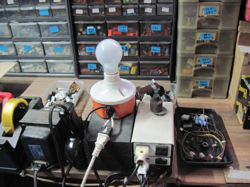
mains bulb tester:
1. i will use a separate filament traffo with 6 or 12 volt output and then inject voltage
to one one of the windings to get readings and find out turns ratios...
do it both ways...
2. knowing the turns ratios, you can then scale it up to your mains line voltage...
3. you can then use the light bulb tester to find out for sure, use the windings
with the highest recorded voltage as your primary winding..
mains bulb tester:

what you have done so far is to identify windings, here is what i will do:
1. i will use a separate filament traffo with 6 or 12 volt output and then inject voltage
to one one of the windings to get readings and find out turns ratios...
do it both ways...
2. knowing the turns ratios, you can then scale it up to your mains line voltage...
3. you can then use the light bulb tester to find out for sure, use the windings
with the highest recorded voltage as your primary winding..
Thanks for sharing your method! I think I can now keep up the work while putting together the bulb tester circuit. I already thought about scaling down voltage to test the transformer with but I wasn´t sure if the results were then easy to scale up or were there going to be some variables that don´t keep the results in scale.
I don´t have a filament transformer at hand now, but I do have other small transformers that put out 12VAC. On measuring the voltage that the transformer puts out it´s more likely to be somewhere around 15-17VAC unloaded. So would I feed the transformer in case with the small 12V transformer and when connected measure the secondary of the 12V transformer to get the exact voltage/scale factor?
K
yes, that will do... good luck, using 12 volts as injection voltage does not require big power and is very safe to use...
1. i will use a separate filament traffo with 6 or 12 volt output and then inject voltage
to one one of the windings to get readings and find out turns ratios...
do it both ways...
By doing it both ways did you mean feeding the 12v supply to the secondary as well as the primaries of the transformer?
K
- Status
- Not open for further replies.
- Home
- Amplifiers
- Power Supplies
- Help Identyifying Power Transformer?