by "do it both ways" i mean use one side as primary, take readings on the other side, then reverse the injection and compare results...
Here we go. I´ll sum up the already gathered information here also with the new AC readings. I had one small transformer that unloaded puts out 16.87V. From now on I´ll refer to this transformer as "small transformer" 😀
TRANSFORMER UNDER INVESTIGATION:
A-X1=PRI1 - DC Resistance 8R4
A-X2=PRI2 - DC Resistance 9R4
A-X3=PRI3 - DC Resistance 10R6
a-x = SEC - DC Resistance 0R1
MEASURED AC READINGS:
Small transfomer loaded with PRI1/PRI2/PRI3 = 16.74V
PRI1->SEC = 1.64V
PRI2->SEC = 1.47V
PRI3->SEC = 1.34V
Small transfomer into with SEC = 13.77V
SEC->PRI1 = 135.6V
SEC->PRI2 = 150.7V
SEC->PRI3 = 166.0V
I did the measurements two times, had bot readings withing 0.1V error margin.
K
You do not connect the primary to the secondary.
It's the complete separation of primary from secondary that defines an isolation transformer.
It's that isolation that helps stop the user killing themselves.
You apply voltage to the primary. You measure open circuit voltage of the secondary.
You apply a load to the secondary and find the loaded secondary voltage, when the primary voltage is held constant.
There is a special class of transformer: auto transformer or auto-former.
This does not isolate the output from the lethal mains.
A Variac is an auto-former.
You do not connect the primary to the secondary.
It's the complete separation of primary from secondary that defines an isolation transformer.
It's that isolation that helps stop the user killing themselves.
You apply voltage to the primary. You measure open circuit voltage of the secondary.
You apply a load to the secondary and find the loaded secondary voltage, when the primary voltage is held constant.
There is a special class of transformer: auto transformer or auto-former.
This does not isolate the output from the lethal mains.
A Variac is an auto-former.
Did I connect the secondary to the primary in any point?
what does this meanDid I connect the secondary to the primary in any point?
Small transfomer loaded with PRI1/PRI2/PRI3 = 16.74V
PRI1->SEC = 1.64V
PRI2->SEC = 1.47V
PRI3->SEC = 1.34V
Small transfomer into with SEC = 13.77V
SEC->PRI1 = 135.6V
SEC->PRI2 = 150.7V
SEC->PRI3 = 166.0V
what does this mean
"Small transfomer loaded with PRI1/PRI2/PRI3 = 16.74V"
16.87V (measured unloaded) secondary of a small 15V transformer fed to the primaries of the transformer in case. The 16.87V dropped to 16.74V when connected to any of the three primaries.
"PRI1->SEC = 1.64V
PRI2->SEC = 1.47V
PRI3->SEC = 1.34V"
16.74V fed to PRI1 (A-X1) -> voltage measured across SEC (a-x). then repeated on PRI2 and PRI3.
"Small transfomer into with SEC = 13.77V"
I wrote that completely wrong there. But same procedure as before. Only this time the 16.87V voltage fed to the SEC (a-x). And this time the voltage dropped to 13.77V.
"SEC->PRI1 = 135.6V
SEC->PRI2 = 150.7V
SEC->PRI3 = 166.0V"
13.77V fed to SEC (a-x) -> voltage measured across PRI1 (A-X1). then repeated on PRI2 and PRI3.
K
OK.
you work out the primary to secondary winding/turns ratio from the opencircuit voltages.
They should be the same on both directions.
Then you see what available tappings on the primary are available.
Probably 5Vac steps, or 10Vac steps. Although your numbers are pointing to 15Vac steps. Unusually large.
OK.
you work out the primary to secondary winding/turns ratio from the opencircuit voltages.
They should be the same on both directions.
Then you see what available tappings on the primary are available.
Probably 5Vac steps, or 10Vac steps. Although your numbers are pointing to 15Vac steps. Unusually large.
That I´ll do.
I´m sorry posting the results/methods used so unclear. Still learning how to present the data.
K
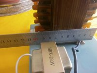
It conferms what I suspected, 220V - 10% , 220V , 220V+10% to 20V no charge and probably 18V full load.
Mona
Mona
OK.
you work out the primary to secondary winding/turns ratio from the opencircuit voltages.
They should be the same on both directions.
Then you see what available tappings on the primary are available.
Probably 5Vac steps, or 10Vac steps. Although your numbers are pointing to 15Vac steps. Unusually large.
So, I´ve put the voltages in order and I hope I´m doing the right ratio calculations:
16.74V fed to the Primaries:
PRI1 - 16.74/1.64=10.21
PRI2 - 16.74/1.47=11.39
PRI3 - 16.47/1.34=12.49
13.77V fed to the Secondary:
PRI1 - 135.6/13.77=9.85
PRI2 - 150.7/13.77=10.94
PRI3 - 166.0/13.77=12.06
So can we say the ratios are:
PRI1 : SEC ->10:1
PRI2 : SEC ->11:1
PRI3 : SEC ->12:1
Am I on the right track?
It conferms what I suspected, 220V - 10% , 220V , 220V+10% to 20V no charge and probably 18V full load.
Mona
Can you tell me how did you come to this conclusion about the 220V? Why could it not be 220V-230V-240V? And wouldn´t the voltage rise closer to 24V after rectification? We here in Finland have 230V mains so if the case case was +/-220V which would be the most appropriate winding to use in the Primary?
K
Last edited:
Connect mains power across the longest primary.So, I´ve put the voltages in order and I hope I´m doing the right ratio calculations:
16.74V fed to the Primaries:
PRI1 - 16.74/1.64=10.21
PRI2 - 16.74/1.47=11.39
PRI3 - 16.47/1.34=12.49
13.77V fed to the Secondary:
PRI1 - 135.6/13.77=9.85
PRI2 - 150.7/13.77=10.94
PRI3 - 166.0/13.77=12.06
So can we say the ratios are:
PRI1 : SEC ->10:1
PRI2 : SEC ->11:1
PRI3 : SEC ->12:1
Am I on the right track?
Can you tell me how did you come to this conclusion about the 220V? Why could it not be 220V-230V-240V? And wouldn´t the voltage rise closer to 24V after rectification? We here in Finland have 230V mains so if the case case was +/-220V which would be the most appropriate winding to use in the Primary?
K
Measure the input voltage and measure the voltage at the two intermediate primary tappings.
Measure the output voltage.
Load it up and measure again.
Not that long ago 220V was the standard voltage, that transfo doesn't look very new, so...Can you tell me how did you come to this conclusion about the 220V? Why could it not be 220V-230V-240V? And wouldn´t the voltage rise closer to 24V after rectification? We here in Finland have 230V mains so if the case case was +/-220V which would be the most appropriate winding to use in the Primary?
K
The output often drops about 10% form no to full charge.That leeds to 18V at Imax.After the rectifier you get (18x√2) minus two diodedrops from a bridge rectifier total 24V.
Depends on the local situation to choose 220 or 240V.The 200V tab can be used too but more loss in the transformer and it could get warmer.
Mona
looks to me you are, now, how heavy is that traffo?
do you have dimensions we can look at?
I will check the dimensions and the actual weight today. I think it weighs about 2.5-3kg
K
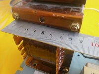
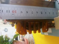
Here´s images of the tree dimensions of the transformer. Weighs just under 3kg. So pretty massive.
About those attachment pieces, clearly visible in the image P6021424 just above the ruler and on the bottom. Can those be removed to make vertical instalment possible? Just as long as the bolts are tightened again after removing the pieces. Thought I would also make a cap for the side of the transfomer that would show.
K
Attachments
ok, you have a traffo good for about 300 volt amperes.....
yes, you can mount them whichever way you like....
yes, you can mount them whichever way you like....
- Status
- Not open for further replies.
- Home
- Amplifiers
- Power Supplies
- Help Identyifying Power Transformer?