
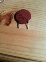
The Sony p/n from the service book is 1-808-65-11 Thermistor, Positive, but not giving many clues on the amperage or such like.
Could it be a PTC thermistor (the opposite of an NTC inrush limiter)?
What is its cold resistance? How does it change if you warm it between your fingers? What role does it play in the circuit?
What is its cold resistance? How does it change if you warm it between your fingers? What role does it play in the circuit?
I think it could be a "positor" which is used in place of a fuse. At currents within its operating range it has a very low resistance, when the current is exceeded the resistance rises dramatically and suddenly.
These devices have to be replaced with one of the correct characteristics for continued protection as they are chosen on voltage as well as current.
Are you sure its faulty ? Have you measured its resistance when cold.
These devices have to be replaced with one of the correct characteristics for continued protection as they are chosen on voltage as well as current.
Are you sure its faulty ? Have you measured its resistance when cold.
Current Murata datasheet suggests the initial character string denotes case style, and AR means 120C. The 0R5 may be its resistance @ 25C. For specification another parameter is required linking power dissipation to temperature, I assume.
The datasheet, available for example from RS, may help selection of a suitable replacement. I don't know enough about PTC thermistors to make a suggestion.
The datasheet, available for example from RS, may help selection of a suitable replacement. I don't know enough about PTC thermistors to make a suggestion.
Hi,
I found not too long ago the attached PDF Posistor application manual that may help you to find what it is. I think they list the PTH in the last line to the right in the variety list. If I am not wrong they used it in motor starters. Good luck.
I found not too long ago the attached PDF Posistor application manual that may help you to find what it is. I think they list the PTH in the last line to the right in the variety list. If I am not wrong they used it in motor starters. Good luck.
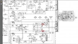
Thanks for your inputs, I cant be sure if its faulty or not but it certainly isn't letting any voltage pass through (highlighted is the two areas where these components sit) it any more than 0.3-0.5v.
The parts in the schematic are PS951 and PS952
I have attached a schematic of the area I am working on, if I am reading correctly there should be 11.9v with the power on between the feeder leg and leg 1 of IC950, currently there is no voltage.
At the Reds to Black (gnd) there is a fluctuation between 11-26 milivolts, should it be this low from a direct feed from the main traffo?
Starting to think now it might be a traffo issue, what's the best way to test?
Oranges both read 26.8v to GND.
Attachments
Hi,
Read the AC voltage at the bridge. If you do not have voltage remove the transformer wires to the bridge and read the voltage. If you have voltage then the bridge it is bad. If you do not read voltage then the trafo it is bad
Read the AC voltage at the bridge. If you do not have voltage remove the transformer wires to the bridge and read the voltage. If you have voltage then the bridge it is bad. If you do not read voltage then the trafo it is bad
That was where I was going wrong with the voltages lol was reading DC with the meter and not AC, I have 10.5v AC at the traffo at the red points now, 10.5v at the start of the bridge and 29.5v (00.2 reversed probes) from the in gate to the out gate , this is with the traffo still in place, is this a normal reading?
I have also noticed that component Q950 is very warm to the touch?
I have also noticed that component Q950 is very warm to the touch?
Last edited:
They are positors or polyswitches as they are sometimes called.
Remember the transformer is AC so set your meter correctly. Should be straightforward to determine the problem. If any of the other rails are present then the tranny is probably OK.
Its either an OC tranny or a short on a rail (which could include the bridge).
Remember the transformer is AC so set your meter correctly. Should be straightforward to determine the problem. If any of the other rails are present then the tranny is probably OK.
Its either an OC tranny or a short on a rail (which could include the bridge).
Posted together 🙂
Measure the output of those two regs. You should have +5 and - 5 volts. If you haven't then measure the voltage at the input to the regs. Should be at least + 12 and - 12. If that's low then measure the voltage at the other side of the positor. If thats high then you most likely have either a faulty regulator (they do fail) or a component within the unit drawing excess current and tripping the positor.
Measure the output of those two regs. You should have +5 and - 5 volts. If you haven't then measure the voltage at the input to the regs. Should be at least + 12 and - 12. If that's low then measure the voltage at the other side of the positor. If thats high then you most likely have either a faulty regulator (they do fail) or a component within the unit drawing excess current and tripping the positor.
Should i measure this in ac or dc, in dc its:
IC951 8.5v inner leg to middle leg, 13.5 middle to outer
IC950 5.5v inner to middle, 13.5 middle to outer
IC951 8.5v inner leg to middle leg, 13.5 middle to outer
IC950 5.5v inner to middle, 13.5 middle to outer
Its DC
With your meter negative lead connected to ground, you should read plus 5 volts on pin 2 of IC950 and minus 5 volts on pin of IC951. (Are those surface mount IC's... the pin numbers aren't what I expected)
With your meter negative lead connected to ground, you should read plus 5 volts on pin 2 of IC950 and minus 5 volts on pin of IC951. (Are those surface mount IC's... the pin numbers aren't what I expected)
The ones im looking at are a 3 pin type
IC950 is a M5F7905 http://images.ihscontent.net/vipimages/VipMasterIC/IC/MITS/MITSD012/MITSD012-5-68.pdf
one of the outer pins is ground the other two read -5.09 -13.79
IC951 is a M5F7805
(cant seem to find a datasheet on this)
center pin is ground other two read 5.02 and 13.52
IC950 is a M5F7905 http://images.ihscontent.net/vipimages/VipMasterIC/IC/MITS/MITSD012/MITSD012-5-68.pdf
one of the outer pins is ground the other two read -5.09 -13.79
IC951 is a M5F7805
(cant seem to find a datasheet on this)
center pin is ground other two read 5.02 and 13.52
For the record those Murata thermos would only measure in AC, my bad for not knowing about AC/DC (other than the band!)
My power issue appears to be coming from a set of ICP-N15 fuses, blocking voltage getting to various IC chips which is stopping things like the sled/chucking/spindle/loading motors and the laser from doing anything, so if you have this issue in your Sony CD Player be sure to check out these fuses, with a little help from some of you good people on here, should have one player up and running again and fingers crossed it was just a short and not some other component that's gone as well, parts should come tomorrow, fingers firmly crossed!
All the best
Stuart
- Status
- Not open for further replies.
- Home
- Source & Line
- Digital Source
- Help identifying a component and its value