Big thanks for your work, lately I can't have time to test the 2 way speaker because my wife had an accident and she is recovering & my listening room share the saloon where is the TV & she is all day watching TV....
Thank me when it's finished and if it sounds good. 😀 Hope your wife is well soon.
Just to finish up, I did a quick sketch of the bottom cab bracing that I would do now that I know the dimensions. With just the matrix bracing, you still have some long narrow panel sections that are free to vibrate so adding 1 cross brace to each of these will do a good job of fixing that. I drew maybe 10mm x 22mm pieces of wood but what's also good are about 22mm round dowels too. What ever works for you. Notice the top and bottom panels lack the cross bracing but one has another cab on top of it and the other is right next to the floor so these are already somewhat attenuated. I calculate about 3.7L for the bracing as I have drawn it. You can probably find a few more small places on the panels here and there to cut out some wood and still maintain structural rigidity. Oh yea, port cut-out needs to be longer than what I've drawn. I've placed it on the back. Closer to the back wall may increase the port output a little but that's a guess.
The drawing uses 40mm on the front baffle and 22mm on the other panels. Bracing is 10mm. An interior volume of 74, 75 or 76L makes no real difference. Line the walls with insulation.
As I mentioned before, you don't need a ported cab for the mid in a 3-way. Sealing it will give it a better transient response and the easiest way to do that is just stuff the port with insulation. However, the box volume for the ported alignment is bigger than what you need for a sealed one although in reality you have a lot of variability to work with with a sealed box. A Q = .5 needs about 10L and a Q = .7 needs about 5L. Depends on the amount of stuffing too. I think your 2-way Vb is about 14 or 15L.
So my suggestion would be to use this extra volume to absorb internal SPL and better soundproof the box. Find some high density insulation, and line the sides, top and bottom with 3-5 cm and the back wall with maybe 10-15 cm thicknesses. Leave about 4-5 L behind the driver clear. Try that. See if you notice a difference and if you like it better. Adjust to taste. My ideal choice for this is Roxul RockBoard with densities from 6 to 8 lb/ft^3 but I don't know if you can find that kind of product in Europe. Maybe this resource will help - http://www.bobgolds.com/AbsorptionCoefficients.htm. Look for insulation that has higher absorption at the lower frequencies. Memory foam mattress topper might work well too.
I'm sure I forgot something so I'll be around for questions. Good luck.
Attachments
I calculate all the woofer cab with 22mm, please could you tell me the measurements for sides, top and bottom cab also could you tell me the dimensions of the rear port and the distance where I have to place?
To work according to my simulation, the front of your speaker should have the dimensions of the first diagram below.
With all panels 22mm thick:
width: 325mm
height: 580mm
depth: 570 - 600mm - your choice, it doesn't make much difference but it's usually better if height and width are not the exact same dimensions.
Still, I would prefer a thicker front baffle but 22mm will do.
You said earlier that you were going to use this port - MBR-80M - Bass reflex tube 54cm² - Europe Audio. Use the full length.
Good question on the port placement - I hadn't given it enough thought in my matrix diagram. Arguably, it's too close to the bottom in those pics. If someone else wants to second that opinion, then maybe putting it above the next horizontal brace would be better, about 200mm or so from the bottom of the cab. I don't know that front or back will make that much of a difference. I don't expect any problems with chuffing at high volumes with that port. At xmax at 102dB, port speed is about 20 m/s. Above 26-28 m/s is excessive. You can put it on the back to be sure and maybe, but only maybe you will get a little extra boundary gain with it being closer to the back wall. If you have a preference for it on the front, then put it there.
Attachments
I'm sorry I didn't expressed well, same dimensions if I want to use 40mm front panel & the rest 22mm?
No problem.
Pretty much the same dimensions. With that volume and port, 1 or 2 liters either way isn't making much difference. And the depth is the only dimension you should vary at this point.
Pretty much the same dimensions. With that volume and port, 1 or 2 liters either way isn't making much difference. And the depth is the only dimension you should vary at this point.

maybe you removed the wrong resistor
you are aware that a series resistor between cap and tweeter will make the cap appear even bigger ? ....so to speak
and to me the series cap already seems very big as is .... but depends on tweeter impedance
is parallel 0.24mH a bit on the small side .... ?
with such fine behaving tweeter, why use notch, LCR, or whatever its doing ?
if not very very finely adjusted, it could make more trouble than good
but it's very easy to try without ... simply disconnect it 😀
thanks tinitus but now I see the problem was not the tweeter sounds bad, the problem is that the cab isn't difracted, surely sounds very good without any series resistor & with the cab chamfered as jReave suggested.
Do you know the brace panels dimensions to do the matrix?
I did that matrix drawing fairly roughly so I don't have exact measurements to give you. Plus you need to decide on the final depth. The vertical brace is in the middle of the front baffle. The top horizontal brace sits at the mid-point of the driver. Position the other 2 horizontal braces so they more or less divide the remaining distance to the bottom of the cab in half. Be sure there is enough space to fit the flared end of the port.
Typically, I will do a final scale drawing on graph paper after I get my material and I measure the exact thickness of what I'm working with and then keep double checking as I make cuts along the way. Give that a try or follow whatever method worked for you on your 2-way build. That looks well done.
I'd probably leave a minimum of 2.5cm of material between the cut-outs and a cabinet panel and between each cut-out. That will determine how large the diameter of the circles need to be in each section of the matrix. So will the placement of the cross braces if you also want to use those as I've drawn them. So the middle of each vertical matrix section will need to be solid wood. Plan accordingly. You can use many different diameters too and even a few odd shaped cut-outs here and there.
Just remember what you are trying to achieve: On the front, back and sides, there is no area larger than about 200mm x 270mm that is unbraced and therefore free to vibrate. The smaller that area, the higher the frequency of vibration and all we want to do is push that frequency above what is being generated in this cabinet - and the xo is at 250Hz. That's one of the advantages of splitting your speaker into 2 sections. And of course, the bracing needs to be strong enough that it doesn't flex, and the rear of the driver and the port opening need to remain as unobstructed as possible. So as long as these goals are met, you can really do whatever you wish.
And I guess I better say as long as the internal volume remains at about 75L too. 😉
thanks tinitus but now I see the problem was not the tweeter sounds bad, the problem is that the cab isn't difracted, surely sounds very good without any series resistor & with the cab chamfered as jReave suggested.
I think what my simulations show is that the diffraction and an unoptimized mid and tweeter xo are giving you a fairly poor result. You have to fix both to improve things. I think it maybe sounded half decent originally because you are using some high quality drivers but it's far from flat.
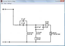
But tinitus is correct. Removing the series resistor before or after the xo has different effects. To let you see visually but this time with a smoother scaling, the 1st graph is your original 2-way again, then with the 3ohm resistor removed, and then with the 3.3ohm resistor removed instead. For present listening, the 2nd one may be a touch too bright making the 3rd one the better choice. Let your ears decide. You actually have more bass than this shows because your cab is presently ported and my sim is with a sealed cab.
Just so you can see, the next 3 graphs are the same conditions again but this time with a 2cm chamfer on the baffle edges. The high end is smoother but the xo is still far from optimal.
Attachments
Yes, those peaks in the mid near the xo region have caused me some headaches. I wanted to cross the mid lower to avoid them but also wanted to cross the tweeter higher to avoid it's rising distortion below 3000Hz. And then there was the baffle difraction on the tweeter too........ 😱
I've tweeked the xo a little bit more (thanks for the suggestions tinitus) and managed something a little smoother but there is nothing I can do about those dips at about 2200Hz and 6000Hz - it is what it is. Lower xo is at about 240Hz and the upper one at about 2500Hz. Sorry for all the components though. And some of the values are pretty high. You may want to be selective in your component choices. I did look on the Europe Audio web site and was happy to see that they have a lot of affordable parts available. For high inductor values, don't use air core unless you've got money to burn and lots of space available. Then it's ok. 😉 If you're going to use higher end caps, the ones in series with the mid and tweeter are more important, C1, C4, C5 and C7.
The wiring diagram is below along with the new graphs. Components are grouped according to their functions. The 2nd last graph shows the dB scale in more detail with a max SPL of about 89dB down low and a minimum of about 86dB in the dips, so pretty smooth actually which is easier to see when you zoom out (last graph). As is there is a tiny bit of a smiley face to the response with a little emphasis in the 60-70hz range, but once you get everything hooked up then it'll be up to you to set the final mid and tweeter levels via series resistors. The level of the bass is pretty much determined by your in room speaker placement. If it ends up a little lower than my simulation, then you'll want to pad down the mid and tweeter a little more. Right now, there is no padding on the mid and only a very little on the tweeter.
Sensitivity looks to be about 87dB and the impedance stays around 5ohm minimum except around 4000Hz where it dips down to 3ohm for a bit. All drivers are connected to positive polarity and the nulls (grey lines) are respectively deep when the polarity on the mid is reversed showing good phase tracking in the xo regions. Power response (green line) could be a little smoother but, best I could do.
There is a little wiggle room when it comes to component values but some of the others need to be bang on. The mid/tweeter xo and the parallel notch filters in series in particular need to be right. Ask me about any changes if you can't find specific values.
Given the quality of the drivers you're using, once this gets all put together it should sound pretty nice. Still, it's based on simulations and not measurements so there is always a chance that it won't turn out exactly as shown. Just fair warning. But for your situation, I think this is the best way for you to go.
R3 8.8 ohm (total is summing the L2 resistance, right?)
R9 13 ohm (total is summing the L9 resistance, right?)
I did that matrix drawing fairly roughly so I don't have exact measurements to give you. Plus you need to decide on the final depth. The vertical brace is in the middle of the front baffle. The top horizontal brace sits at the mid-point of the driver. Position the other 2 horizontal braces so they more or less divide the remaining distance to the bottom of the cab in half. Be sure there is enough space to fit the flared end of the port.
Typically, I will do a final scale drawing on graph paper after I get my material and I measure the exact thickness of what I'm working with and then keep double checking as I make cuts along the way. Give that a try or follow whatever method worked for you on your 2-way build. That looks well done.
I'd probably leave a minimum of 2.5cm of material between the cut-outs and a cabinet panel and between each cut-out. That will determine how large the diameter of the circles need to be in each section of the matrix. So will the placement of the cross braces if you also want to use those as I've drawn them. So the middle of each vertical matrix section will need to be solid wood. Plan accordingly. You can use many different diameters too and even a few odd shaped cut-outs here and there.
Just remember what you are trying to achieve: On the front, back and sides, there is no area larger than about 200mm x 270mm that is unbraced and therefore free to vibrate. The smaller that area, the higher the frequency of vibration and all we want to do is push that frequency above what is being generated in this cabinet - and the xo is at 250Hz. That's one of the advantages of splitting your speaker into 2 sections. And of course, the bracing needs to be strong enough that it doesn't flex, and the rear of the driver and the port opening need to remain as unobstructed as possible. So as long as these goals are met, you can really do whatever you wish.
And I guess I better say as long as the internal volume remains at about 75L too. 😉
I don't ask the matrix dimensions, I only want to know the inside distance between front and rear cab, side to side cab & top to bottom cab to know how calculate the matrix structure.
Last edited:
R3 8.8 ohm (total is summing the L2 resistance, right?)
R9 13 ohm (total is summing the L9 resistance, right?)
Correct. You already have L2-C3-R3 on your tweeter now. So L9 doesn't need to be an expensive low resistance inductor. Just subtract whatever value it is from 13 to get R9's value.
Also, I figure you already know that you can parallel caps to sum their values. So you can use anything you already have and just buy the values necessary to add up to your new ones. And just in case, resistors in series will also add up so you will want to have a few extra 1ohm and maybe .5ohm on hand to adjust the mid and tweeter levels by ear after everything is set up.
I wasn't sure what might be available to you so I put in .5ohm for L7 and L8 on the woofer circuit, but if you can get lower ones than that, that will be better.
Schematic below again for easy reference.
I don't ask the matrix dimensions, I only want to know the inside distance between front and rear cab, side to side cab & top to bottom cab to know how calculate the matrix structure.
Just take your outside dimensions and subtract whatever the panels actually measure.
So if panels = 22mm and front baffle = 40mm, and
outside height = 580mm
outside width = 325mm
outside depth = 590mm, then
inside height = 536mm
inside width = 281mm
inside depth = 528mm, and
net cabinet volume=~ 75.5L
Attachments

What's L4 value?
Oops, sorry, I listed L4 as L3. Changed schematic attached. 😱
L4 = 12mH (.5ohm)
Attachments
To work according to my simulation, the front of your speaker should have the dimensions of the first diagram below.
With all panels 22mm thick:
width: 325mm
height: 580mm
depth: 570 - 600mm - your choice, it doesn't make much difference but it's usually better if height and width are not the exact same dimensions.
Still, I would prefer a thicker front baffle but 22mm will do.
You said earlier that you were going to use this port - MBR-80M - Bass reflex tube 54cm² - Europe Audio. Use the full length.
Good question on the port placement - I hadn't given it enough thought in my matrix diagram. Arguably, it's too close to the bottom in those pics. If someone else wants to second that opinion, then maybe putting it above the next horizontal brace would be better, about 200mm or so from the bottom of the cab. I don't know that front or back will make that much of a difference. I don't expect any problems with chuffing at high volumes with that port. At xmax at 102dB, port speed is about 20 m/s. Above 26-28 m/s is excessive. You can put it on the back to be sure and maybe, but only maybe you will get a little extra boundary gain with it being closer to the back wall. If you have a preference for it on the front, then put it there.
Attached the real placement of tweeter & mid-woofer, the placement you posted is wrong
Attachments
You said earlier that you were going to use this port - MBR-80M - Bass reflex tube 54cm² - Europe Audio. Use the full length.
Good question on the port placement - I hadn't given it enough thought in my matrix diagram. Arguably, it's too close to the bottom in those pics. If someone else wants to second that opinion, then maybe putting it above the next horizontal brace would be better, about 200mm or so from the bottom of the cab.
200mm of the centered port hole to bottom?
- Status
- Not open for further replies.
- Home
- Loudspeakers
- Multi-Way
- Help for 3 or 4 way loudspeaker