I am not 100% sure but yes, I think a 2cm 45º chamfer on just the top and sides will be ok. That should just be a very small difference.
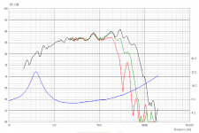
Perhaps as a test to know if my sims are matching reality, you might try your current xo with the 2.2ohm or the 3.3ohm resistor removed. This will bring the tweeter level up to about the same level as the mid. If you think it sounds better then we're good. If you think it sounds too bright, then we probably have a problem somewhere. Graph shows my sims with your current xo with the 3.3ohm removed.
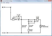
Thanks, attached actual xover for 2 way cab, wich xover for the woofer? my 2 way cab have BR in the rear side, have I to close?
Attachments
Last edited:
hi, jReave
hope you don't mind me asking
have you built speakers this way ?
experience with how a simmed response curve will sound in real life ?
just very curious to know how well sim technology works
For the xo sims, I'm using Passive Crossover Designer, Loudspeaker Design Software. This is a free excel program that is really an amazing tool and has an outstanding reputation for success. But the old saying applies: garbage in = garbage out. One needs to feed it files that are as accurate as possible. Real measurements are best but in their absence, I'm using various other programs, like SPL Trace, Unibox, the Edge, Baffle Diffraction Simulator and Frequency Response Combiner.
FRD Consortium
jbagby
If you look here, https://sites.google.com/site/undefinition/simulated-measurements, this gives an excellent overview as to the accuracy of the simulated frequency responses vs real measurements.
Me, I've still got lots to learn, but given merlin's situation, I think using these tools is the best way to go. I can't get a perfect model on the 3-way cabinet shape and it's baffle diffraction but pretty close and I'd be slightly more confident if I was using a 3rd party's measurements of the Scan 18W8545 instead of the manufacturer's graphs, but it's still a world above on-line xo calculators. The exact amount of baffle step compensation is hard to know too so it's going to be up to merlin to make any necessary tweeking to mid and tweeter levels via resistor choices.
But like I said in my previous post, if my sims aren't matching his current 2-way, then I should probably go back to the drawing board. 😉
Thanks, attached actual xover for 2 way cab, wich xover for the woofer? my 2 way cab have BR in the rear side, have I to close?
I'm trying to make sure that my simulations are in the ballpark before I give you new xo parts and values to spend a bunch of money on. My sims show your tweeter level to be a little low so try removing 1 of those series resistors and see how that sounds to your ears. If that doesn't sound right, if the tweeter sounds much too loud, then something is wrong and I can't recommend my simulated xo. Too bad you can't take measurements, but then if you could, you probably wouldn't need my help.
Yes, I was going to get to your mid cab shortly. You don't need it ported as a mid in a 3-way. Easiest thing to do is to just stuff the port and add extra insulation to the cab. I'll suggest more on it later.
But like I said in my previous post, if my sims aren't matching his current 2-way, then I should probably go back to the drawing board. 😉
ahh, you are using the 2way as is ... or was
well, hate to say it, but tweeter rolloff looks a bit 'off'
ever thought about a complete 3way redesign ?
or if the 2way is ok and sound good as is, maybe 'just' use active plateamp for the woofer ?
(btw, thanks for explaining)
No, I simmed the 2-way as is just to use as a starting point. It didn't look very good.
So, yes I re-did the whole xo with and without chamfers on the baffle and with different levels of BSC.
Now I'm waiting for a reality check.
So, yes I re-did the whole xo with and without chamfers on the baffle and with different levels of BSC.
Now I'm waiting for a reality check.
So, yes I re-did the whole xo with and without chamfers on the baffle and with different levels of BSC.
this one I guess
I don't recall having seen the xo
hmm ... looks to me like the mid have a bump in the stopband, causing a peak in response curve
my estimate is that if you deal with that mid 'bump' a few things might turn out different ... maybe
Attachments
I don't recall having seen the xo
hmm ... looks to me like the mid have a bump in the stopband, causing a peak in response curve
my estimate is that if you deal with that mid 'bump' a few things might turn out different ... maybe
Hadn't posted the xo yet. But yes, that mid has a resonant peak at about 750Hz and baffle diffraction is hitting it right at that point too. Right now merlin's xo is attacking it with a series LCR placed in parallel to the driver with middling results.
I've used a parallel LCR in series after the xo to achieve a much flatter result (big cap required) that I didn't think needed much more work. No resistance on the mid right now, but I figured to use that only if required by ear.
Graph below shows the mid FR with and without the filter. Second shows the xo components used.
I'll post the whole thing soon, I'm in the middle of a busy day right now.
Attachments
But yes, that mid has a resonant peak at about 750Hz .....
no, in the stopband above xo point
in tweeter passband ... 2.5-3Khz
it 'forces' you to roll off the tweeter too early, and causing another 'bump'
if not absolute necessary, I would try without notch filters etc
I never use 'clean' 12db, 2. order
but always prefer the sound when making the parallel component a zobel instead
actually, I always mount a resistor in series with parallel components, be it parallel capacitors or inductors
Attachments
Thanks tinitus, that's helpful. Sorry, I misunderstood.
I'll try a few more things. I definitely found the zobel to be helpful. Do you have any specific ideas I should try out?
I'll try a few more things. I definitely found the zobel to be helpful. Do you have any specific ideas I should try out?

Thanks guys.
jReave I have to do the test with chamfered edges right?
No, i'm just trying to check the accuracy of my simulations. Your current 2-way xo as you have shown it looks to have too low a tweeter level.
I'm pretty sure there's an error of some kind here. Your tweeter is about 89dB sensitivity (Zaph's test looks closer to 87dB) and the Scan 18W8545 is about 87dB sensitivity. So there's no way that you should have over 5ohm of series resistance on that tweeter to make it match that mid.
If you think the 2-way sounds perfect now, then don't do the test. No point. I think I can say that my sims are correct, but I may somehow be feeding it some wrong info. I'm not sure what right now though. I'll get back to you.
merlin,
Sorry, I had a busy day yesterday.
If you are happy with your current 2-way, then that tells me that something is wrong with my simulation. I am confident that all my files are correct, so that leaves only 2 possibilities. I have either input your current xo incorrectly or something in your diagram is incorrect. Your mid and tweeter are close to the same level with 1W/1m, so over 6ohm of resistance in series on the tweeter has to be wrong.
Here's how I've input your tweeter xo and the result:
Attachments
So, again if you are happy with the way that your current speaker sounds, then here is the same xo with the addition of the woofer. No chamfer on the 2-way baffle.
Ignore the poor high frequency response.
Ignore the poor high frequency response.
Attachments


Those are the best results my xo design skills have been able to come up with. Any suggestions or critiques are welcome.
Felipe, have a look at the graphs and the xo's for each one. I'm trying to give you a choice here on how you want to proceed. Let me know which version you are interested in and I can post the wiring schematic for that xo and even try to tweek it a little more too and go into more detail about it for you.
It took me a while but I hope that helps. 🙂
Now with the top cabinet with a 2cm chamfer, I'm able to smooth out the response a little more.
I like this one, thanks🙂
I don't know if can help to designd the xover, looking for information at tne net for SS18W/8545-00 I got that have three peaks (+4dB, +5dB and +6dB) respectively at 750Hz, 1,8kHz and 2,9kHz
Attachments
Last edited:
Yes, those peaks in the mid near the xo region have caused me some headaches. I wanted to cross the mid lower to avoid them but also wanted to cross the tweeter higher to avoid it's rising distortion below 3000Hz. And then there was the baffle difraction on the tweeter too........ 😱
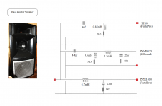
I've tweeked the xo a little bit more (thanks for the suggestions tinitus) and managed something a little smoother but there is nothing I can do about those dips at about 2200Hz and 6000Hz - it is what it is. Lower xo is at about 240Hz and the upper one at about 2500Hz. Sorry for all the components though. And some of the values are pretty high. You may want to be selective in your component choices. I did look on the Europe Audio web site and was happy to see that they have a lot of affordable parts available. For high inductor values, don't use air core unless you've got money to burn and lots of space available. Then it's ok. 😉 If you're going to use higher end caps, the ones in series with the mid and tweeter are more important, C1, C4, C5 and C7.
The wiring diagram is below along with the new graphs. Components are grouped according to their functions. The 2nd last graph shows the dB scale in more detail with a max SPL of about 89dB down low and a minimum of about 86dB in the dips, so pretty smooth actually which is easier to see when you zoom out (last graph). As is there is a tiny bit of a smiley face to the response with a little emphasis in the 60-70hz range, but once you get everything hooked up then it'll be up to you to set the final mid and tweeter levels via series resistors. The level of the bass is pretty much determined by your in room speaker placement. If it ends up a little lower than my simulation, then you'll want to pad down the mid and tweeter a little more. Right now, there is no padding on the mid and only a very little on the tweeter.
Sensitivity looks to be about 87dB and the impedance stays around 5ohm minimum except around 4000Hz where it dips down to 3ohm for a bit. All drivers are connected to positive polarity and the nulls (grey lines) are respectively deep when the polarity on the mid is reversed showing good phase tracking in the xo regions. Power response (green line) could be a little smoother but, best I could do.
There is a little wiggle room when it comes to component values but some of the others need to be bang on. The mid/tweeter xo and the parallel notch filters in series in particular need to be right. Ask me about any changes if you can't find specific values.
Given the quality of the drivers you're using, once this gets all put together it should sound pretty nice. Still, it's based on simulations and not measurements so there is always a chance that it won't turn out exactly as shown. Just fair warning. But for your situation, I think this is the best way for you to go.
Attachments

- Status
- Not open for further replies.
- Home
- Loudspeakers
- Multi-Way
- Help for 3 or 4 way loudspeaker