okay ive just tried that. I used a 15amp fuse. when i first switched it on the gains were set near to full and the fuse blew so i turned the gain down and tried again with a 15amp fuse. i could hear the sub playing a little, the music was on low volume, but it was not to the beat of the music it was a constant on off beat. It did not get louder if i turned the volume up a little and also the positive rail off fets were getting very hot. but when there was no audio input (rcas) connected or sub the amp stayed cool. :S
With no RCAs plugged in and no power applied, measure the resistance from the B+ terminal to the RCA shields. What is it?
What are you using for a signal source?
What are you using for a signal source?
are the RCA sheilds the inside connector or the outer on the plugs? i was using my headunit which is an alpine 9857r, the sub volume was set to abt 5 on the H/U.
The shield is the outer part of the connector.
Also test the shields on the head unit:
http://bcae1.com/images/rca/temporaryrcashieldrepair.html
Also test the shields on the head unit:
http://bcae1.com/images/rca/temporaryrcashieldrepair.html
ive just checked the from the B+ terminal to the rca shields using my analogue meter on its lowest resistance setting, as im not sure what setting to put the new digital meter on, and the meter showed 12ohms.
when i tested the speaker channels earlier before connecting the sub, i forgot to include in the post, that the meter did not pick up a rating from the channels. but i still tried with the sub. Ive current got another, smaller, amp connected in the car to a sub and that works fine... but would i still need to check the RCA shields on the headunit?
when i tested the speaker channels earlier before connecting the sub, i forgot to include in the post, that the meter did not pick up a rating from the channels. but i still tried with the sub. Ive current got another, smaller, amp connected in the car to a sub and that works fine... but would i still need to check the RCA shields on the headunit?
If you power up the amp (no RCAs), do you read approximately 12v on the shield of the amp (black probe on chassis ground)?
What does you analog meter read if you touch the probes together?
What does you analog meter read if you touch the probes together?
analog meter reads 0 when probes are touched together. just checked with red probe on sheild and black on chassis ground terminal and i was getting -48.4v. sounds really high if you said its meant to be around 12v and also it was showing it in minus....i checked with the digital meter and analog(set to show 10v max as other settings dont work) and both show it in minus.
With no power applied with the amp oriented as it was in the first photo you posted. What resistance do you read from the left side windings to the right side windings for the top transformer?
For the bottom transformer?
For the bottom transformer?
where would i put the probes to test the transformers? would i need to take the board out of the amp again to get to the contacts of each transformer? thanks
If you read 0 ohms from the primary to the secondary, you almost certainly have a shorted transformer. Is there any winding on either transformer that has the enamel flaking off?
With one probe on the secondary (left side) and one probe on the primary (right side), twist/push/pull the transformers to see if the short intermittently breaks. If you are working alone, solder wires between the board and the probes so you have a solid connection.
With one probe on the secondary (left side) and one probe on the primary (right side), twist/push/pull the transformers to see if the short intermittently breaks. If you are working alone, solder wires between the board and the probes so you have a solid connection.
with the amp the same way around as my first picture i posted the transformer at the top, (nearest to the FETs that i have changed) looks like its burnt alil
heres a pic:

while the other one looks all clean and black. But would both of them have blown or is it the blown one showing that the other is blown too? where would i be able to get a replacement for these?
heres a pic:
while the other one looks all clean and black. But would both of them have blown or is it the blown one showing that the other is blown too? where would i be able to get a replacement for these?
oops sorry didnt know that. how would i test the transformers then as they seem to have 6 connections to the board? where would i put the probes?
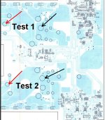
okay so test 1 from your pic was showing me around 12 ohms using the digital meter on the 200k setting and test 2 was showing around 14ohms... but both were increasing slowly. im not sure if this right though as using the analogue meter, i got around 40 ohms for both? but im not sure.
Remove rectifiers D806, 807, 808 and 809 and test them with your digital meter set to the highest resistance scale. Use the form on the following page. Click the link indicated by the yellow arrow. Read and follow the instructions in the yellow box. Post the screen caps (read the instructions) for all 4 rectifiers.
With the rectifiers out, do you still read 12-14 ohms across the test points?
With the rectifiers out, do you still read 12-14 ohms across the test points?
Attachments

- Status
- Not open for further replies.
- Home
- General Interest
- Car Audio
- Help fixing Alpine MRV 1507