Well, as I said, I ordered capacitors for this and it would have to wait a week. I had moved onto other things and had to setup for this test again. I didn't pay enough attention and connected the power transformer incorrectly and it smoked and blew the fuse. After reconnecting the power transformer correctly when powering up, the D2 bridge went up in smoke and who knows what else. This project is on hold until after the re-cap and further repairs are made!
Sorry... Gary
Sorry... Gary
Well, that's sad. The fuse protected the wires but it didn't protect the silicon. I'll be around when you get back on it. I think we were almost there.
Phew! After D2 blew up in my face, then replacing R45 and R10, then having C15 blowup in my face. After which, C8 also blew up in my face while taking out Q7 that I didn't have. I then substituted Q7 with a MPS A93 and the +/- 15v supply works again! Please see attached for the scope shots you requested. I am not going to work on this until the re-cap is completed. The amplifier is functioning the same as before my mishap.
Attachments
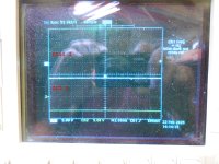
I can't tell what is happening on a 50V/div scale but don't worry about it. I should have been more specific. What I would like to see is a 2V/div DC coupled plot with the scope ground on the negative 62 volt rail showing Pin 3 of IC2 and Pin 6 of IC2. That way I could see the Output pin Pin3 and compare it to the input pin Pin6. Anyway, report back when you are ready to try again.
Hey Gmaff. Do not tie your scope ground to the negative rail if you intend to get this data. It is too dangerous. It is too easy to touch the wrong ground and get shocked. You should use 2 probes and the difference function on your scope. You are probably a better technician than I am so you may not need this advice but I wanted to retract my statement about tying your scope ground to the negative rail.
Last edited:
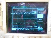
Well, your data shows that something is happening on those pins. A logic pin should be either high or low and neither of these pins look they are at the negative rail or at the SD5V supply. It still looks like they are being linearized. You can see that the pins are actually locked in phase so they have something in common driving them. I think that you need to trace the circuit on those 2 nodes (Pin1 of IC2 and Pin1 of IC11) and discover what parts they have in common. The failed component/s are likely in a shared circuit by these 2 pins. There are some transistors that you can test that may be in the common circuit. They are Q15 and Q17. If you are sure that SD5V is good then the problem is in the circuit/s driving those 2 shutdown pins.
Last edited:
I can't find Q15 or Q17 on the schematic (been through it 3 times). I must be blind or something. I do suspect SB5v though. Yesterday, I carefully tacked leads to IC12 pins 1 & 2 to view on the scope. There were no shorts or anything and just trying to view these signals the FET exploded (see attached photo). The added capacitance from the scope probes was enough to kill the oscillator and blow the output FETs. I need to know if the 100khz oscillator will run without these output devices?
I am really disgusted with Class D amplifiers as this one is poorly designed and highly unstable. It seems to me that the 100khz oscillator is a critical part and should be of solid design not using inverter delay feedback loops.
I have put a lot of time and effort into this, and it is getting very close to the circular file!
Attachments

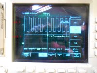
I saw Q15 and Q17 on your picture of the circuit board. They may not be on the schematic as you suggested. It is odd that one channel started to work.. The other channel should also be 100khz. No, the circuit will not oscillate without output fets. There is no onboard oscillator. It oscillates at some high frequency when the output is fed back to the input in a closed loop. It looks like both circuits are oscillating but one is stuck at the low frequency.
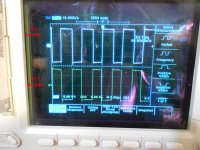
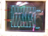
Replaced Blown output FETs. Waveforms look great! (Best ever!) See photo. I would say the amplifier was fixed except those dang output filter 40uH coils are HOT! I never found any bad components, shorts etc. It is possible there was a bad connection in the SB5v circuit which I'm pretty sure I checked and resoldered. I may have missed Q11 though as it is kinda hidden. There could still be an intermittent device in the SB5v circuit. I really need to know if it is normal for the core of the inductors to reach 100 degrees C.
Attachments
It does look good for the moment. I don't know that much about inductors but silicon is allowed to run at 125 deg C safely so it seems that a passive part could operate safely at that temperature. There is the possibility that the frequency is supposed to be faster but we don't know that. Found this: Commercial rated inductors may have temperature ratings up to 85° or 105°C, while industrial inductors have a maximum temperature rating of 125°C, typically.
Thanks for all the help! "James361". At this point, the amplifier is working, and I brought it to my sons to listen to it. It is okay, but maybe a little distorted. I have done all I can do and can't put any more time into it. I have learned a lot about "Class D" amplifiers, so, it was a good exercise. Whoever reads this thread and wants a challenge cleaning up the distortion can have the amplifier, spare parts, my documentation and email address for the actual cost of shipping.
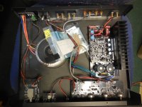
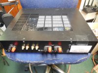
See attached photos of amp, parts and docs. If no one wants it, I'll put it on ebay, CL or just toss it.
--Gary +++++END OF THREAD+++++
See attached photos of amp, parts and docs. If no one wants it, I'll put it on ebay, CL or just toss it.
--Gary +++++END OF THREAD+++++
Attachments

- Home
- Amplifiers
- Class D
- Help! Fixing a "James" Discrete Class D BTL Subwoofer Amplifier