It seems dangerous to do that since it may have a good reason for trying to be in shutdown. Don't remove the diodes. Find the +15V and make sure that it is there. Then see if the R_CUT signal is low at about 1V. If R_CUT is 1V then that points to the opto-coupler being leaky or shorted.
Last edited:
R-Cut circuit?
The opto does not exist on this board (reason for dotted line around it?). No D9 but there is a D19 connected to R52 which connects to Q17 (not on schematic?). I'll have to try to figure it out tomorrow.
The opto does not exist on this board (reason for dotted line around it?). No D9 but there is a D19 connected to R52 which connects to Q17 (not on schematic?). I'll have to try to figure it out tomorrow.
+15v is okay. The auto-sense does not work. Sometimes I need to bump up the level control to kick in the output.
I don't understand the amplitudes of pin 5 & pin 6 of IC10. They appear to be about 0.6V. The logic chip cmos 'AND' gate TC7WH08FU should drive to its Vcc of 4.57v.
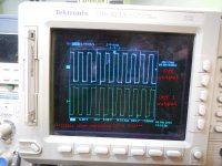
I think we are on the right track. The common denominator may be the R-Cut signal possibly affecting both the positive and negative amps per my scope shot of the outputs being asymmetrical. Unfortunately, that signal is not correctly documented in the schematics and will be hard to trace.
Thank you so much for helping on this! This amp belongs to my son, and I am helping him with it to learn more about class D amplifiers.
--Gary
Thank you so much for helping on this! This amp belongs to my son, and I am helping him with it to learn more about class D amplifiers.
--Gary

I just discovered that in your first post that you had frequencies of 1.8 Khz and 360 Hz. I gave you some bad advice because I read 360 Khz. I thought that one channel was fine and running at 360 Khz. I am sorry about that. I don't see as well as I used to. We wasted some time for that mistake. There isn't much left to check. I think that this amplifier should run in the 100 Khz range so it is surely being throttled back. I know that D19 will shut down one channel when it is pulled low. The other diode is a mystery because it ties to a different point which is either an error or a different function. Maybe one or both channels are supposed to be in shutdown but the shutdown circuit is marginal. I don't know the risk of taking those diodes out. They may be part of a startup sequence or a current or a thermal protection circuit. See if you can do some tracing. We need to know what those diodes are doing.
I agree that both channels should be running around a 100khz and I don't know what components determine that frequency. That being said, the story gets worse. My son bought this amp at an electronic surplus store from a stack of 15. I got the schematic from "James" the manufacturer, but they were not technical and of no help. This amplifier may have been built incorrectly and was defective from the factory. When my son brought it to me, he had replaced the FET's. I really don't know what state it was in when he first looked at it. I am not an EE but worked as a highly skilled Engineering technician for 30 plus years. Repairing electronics is one thing, but solving a design problem is a much greater endeavor. I am 68 now and I too don't have the vision of those early days. I found this interesting tutorial on class D amps and the sample design on page 50 is almost identical. Please see attached.
Attachments
On page 1 of the "James" schematic there is an opto Q9 for "30hz cut". There is another opto Q3 for "remote on" (located on small boards on rear panel). These jacks are labeled 12v. I tested these. For "30hz cut", I set my audio generator for 24 hz and applied 12v and the output signal dropped by 50%. I applied 12v to the "remote on" and it will power up when 12v is applied. I then set my audio generator to 80hz and turned the crossover knob down to 30hz and observed the output gain reduce as well. As you say, the switching frequency is way off, more so on one channel. What components determine this frequency? It seems IC4 and IC13 are not working correctly. D7 and D19 are present but the opto is not and their cathodes are not tied together as the schematic suggests.
I see. That page 50 schematic is the basis for this amplifier. I am almost your age and I was an electronic design engineer so I am sure that we can fix this amplifier with enough effort. I think that I need to study the published schematic some more and see what kind of protections they claim to have. That diode or diodes should go to a protection circuit or an enable circuit. I think that you should scope all of your regulated voltages to see if any have unusual voltage ripple. High ripple can make circuits act incorrectly, If you want to save time and go for broke then you can pull out D19 and see what happens. What ever it is protecting would be defeated but it would give another data point about the low frequency. I will check in some time today after I study the schematic. I love a challenge.
The frequency is basically set by delays in the circuit. The output feeds right back to the input so it runs as fast as it can go. The op amp probably creates the most delay as it is a linear device in the loop.
The frequency is basically set by delays in the circuit. The output feeds right back to the input so it runs as fast as it can go. The op amp probably creates the most delay as it is a linear device in the loop.
Well, I find no protection circuits present in the schematic so D19 much be part of a sequencing loop. They want to enable the switching outputs after some condition which is likely after some supply has reached its operating voltage. It may be sensing itself by forcing D19 to charge a capacitor until the threshold of the logic gates is reached. Both outputs would be affected if these diodes were tied together. I might get a clue if you scope both ends of D19. Also, with the power off, measure the dc resistance of both ends of D19 to the negative power rail.
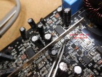
I spent the morning meticulously verifying and testing everything between IC13 and IC12 and painfully removing the transistors (SOT-23) to test out of circuit. Before retesting I installed new "F04's" (IC12 & IC3).
Attachments
Nice. I don't know much about inductors but it might be normal. It does seem pretty hot but they could have designed it that way. Do you know what fixed the amplifier? It seems like it just started working. I saw that you changed parts but it seems odd that both channels would fail the same way. Did you tinker with D19?
False alarm! I looked at it again and there was a lot of jitter on one channel then it dropped back to the low frequencies again. When I lower the AC line voltage to around 80VAC the frequencies go up to about 20khz. I think I should replace all the smaller electrolytic caps with low ESR types. It would be cheap and easy and shouldn't hurt any. This sure seems like a power supply noise issue.
I ordered 26 new caps and the chips. Total cost $15.00. Won't be back on this for a week. Stay tunned!
I don't understand why your output swings 16V or 160V. If your rails are 63V then both rails combined would be 126V. There is a 34V difference here. Could you possible have 34V of power supply ripple on your rails? Either that or your scope or probe is un-calibrated.
Hi, I'm not sure on this. My scope agrees with my Fluke meter which is accurate. The rails are +/- 62v. I do remember measuring 80v somewhere. One problem is my scope is grounded to the chassis ground as the dc reference is not tied to chassis. I need to get differential probes but the Tektronix ones are very pricey. I replaced the F04 inverter chips and that's what got it running. The F04 may not be getting a valid TTL transition or it failed. When I measured 80v I may have used chassis for reference. It's risky to probe that oscillator as the thing blows up if the oscillator stops. I did buy more of the chips.
It would be helpful if I could see the scope plots of Pin 1 of IC11 and Pin 1 of IC2. It seems likely that both of these pins are being linearized around their logic thresholds. That condition is a good possibility for the frequency to be stuck at a low level. If it is linearized then you will have to trace the components on those nodes to see what is holding them down at their thresholds. If IC11 and IC2 are not linearized then that would leave IC12 or IC3 as the parts that are being linearized.
- Home
- Amplifiers
- Class D
- Help! Fixing a "James" Discrete Class D BTL Subwoofer Amplifier