The last time I heard the noise I managed to power the preamp off, the noise continued. Would doing so not isolate everything past the preamp? The power amp was still on, connected to the L/R speakers.From your original description of the fault (post #1) I still suspect that something external to the amp is likely to be the cause but it is very difficult to easily prove that.
It would be worth seeing if the problem occurs at certain times of day or when you have certain household items running.
@johmmath suggested using shorting plugs on the inputs and running the amp in isolation to see if it buzzes. That would be the first thing I would do tbh, you have to try and prove whether the problem with the amp or external to it. It has to be just the amp and speakers and with nothing else external connected to it.
Unless the power amp itself is picking up interference somehow, or the RCA connectors. I ordered some XLR's to see if using those stops the noise.
I re routed my entire systems wiring and put bridges under the power wires several weeks ago, and made sure no two wires contact others.
It didnt help.
BUT, I do have a wall mounted LCD TV that swivels away from the wall a couple feet. And puts the LCD about 1' directly over both amplifiers! Needless to say its time to move one or the other.....
There is a small possibility that the noise is injected through a ground loop even when the preamplifier is off, especially if using RCA inputs. The only way to 100% isolate the noise problem to the internals of the amplifier is to hear the buzz when nothing other than the loudspeakers are connected and preferably the inputs are shorted. Unfortunately, because of its intermittency, absence of the buzz doesn't prove much, but hearing it in this condition is definitive.
This state of the system will allow you to establish its "noise floor". It is good practise to add only one component at a time and check that each additional component does not introduce any changes to the character of the noise floor. If connecting something does, there is a likely a problem that needs sorting out. Often in a system with many component there are multiple issues and they become very difficult to troubleshoot because they are overlaid and interactive, especially ground loops in systems with a mains ground connection.
This state of the system will allow you to establish its "noise floor". It is good practise to add only one component at a time and check that each additional component does not introduce any changes to the character of the noise floor. If connecting something does, there is a likely a problem that needs sorting out. Often in a system with many component there are multiple issues and they become very difficult to troubleshoot because they are overlaid and interactive, especially ground loops in systems with a mains ground connection.
There is a small possibility that the noise is injected through a ground loop even when the preamplifier is off, especially if using RCA inputs. The only way to 100% isolate the noise problem to the internals of the amplifier is to hear the buzz when nothing other than the loudspeakers are connected and preferably the inputs are shorted. Unfortunately, because of its intermittency, absence of the buzz doesn't prove much, but hearing it in this condition is definitive.
This state of the system will allow you to establish its "noise floor". It is good practise to add only one component at a time and check that each additional component does not introduce any changes to the character of the noise floor. If connecting something does, there is a likely a problem that needs sorting out. Often in a system with many component there are multiple issues and they become very difficult to troubleshoot because they are overlaid and interactive, especially ground loops in systems with a mains ground connection.
Noted, I will try running that way, power amplifier > speakers. If I can settle not running playing music on it. For as long as it takes, until I'm satisfied. Thats what made me think I was in the clear the last time. This could get annoying, the idea is not to let it.
I forgot to mention earlier, I have tandem isolated AC lines along the system wall, right behind it. That answers the previous mention about potential interference from other rooms. Through all the different systems that had more and less components hooked up, I never encountered a ground loop in this house ever. But never say never.
Atm system is very minimal, while trying to catch that. Music server/DAC to on the amps on the opposing iso oulet across the room, source to preamp to power amp to speakers. SACD player is cord-less, romoved.
I got to say night time is always the right time, for the power grids having less traffic. Its quiet man, I can't emphasis that enough. You wouldn't think anything is a miss with the amp. Most of the time it is, these are known for having crazy low
noise floors. I don't feel XLR would benefit much if any. Had it not been for the issue I XLRs wouldnt of entered mind.
When I think its h*lla quiet during daytime I just have to try it at night, wow.
I will not excuse anything, and I very much appreciate all those who pitched in.
I thought the close proximity of the LCD display would get a mention, that seems plausible no? I've been meticulous with everything but missed considering the TV, oops.
Side side note, with amplifier being relatively new I don't have that much experience with it, it can be a bit touchy with current I already found out, if your not carful it will let you know, with a startle. I try to handle with care always, I mean one dumb mistake can mean poof!
The lack of speaker relays was some indication to, its build for business and that usually means higher sensitivity to its outside world, and it can grab outside interferences that much better. I think you guys could be on to something also for those reasons. I hope its right and I dodge a bullet with it, Its getting long in the tooth but word is there pretty reliable amps. Lots of people are still using them, build is late 90's early 2000's.
Last edited:
RCA coax cables can pick up high frequency noise from digital products. Modern TV's and D/A are digital products. Buying a RCA plug, shorting across it with a short wire, and listening to the amp for hours for the buzz is the way to eliminate the RCA cable as the antenna. You'll need a soldering iron, wire, solder, safety glasses. The ML 431 schematic does have a pi filter of two 100 pf caps with 100 ohms between them series the center of the RCA jack, to eliminate this problem in circumstances for the date the amp was made. There is more digital hash from products now than was common in the nineties or oh-ohs.
Speaker wires can pick up digital noise. Many amps have a coil near the speaker terminals, series the output, about the size of a AA battery. This is to keep RF interferance from speaker wires out of the amp. I don't see such a coil in the Mark Levinson 431 schematic, and I don't see two in the picture near the binder posts (outputs). They might be behind the red capacitor in the picture. Short wires (1 foot) to a test speaker is the best you can do on that, to eliminate speaker wire as the antenna that picks up a buzz. You can pick up such a test speaker at a charity resale shop, probably for $2 or so.
I've had to add a coil behind the speaker jack to the output of an amp that didn't have one. That one was picking up sports talk AM radio from the 10 meter speaker wires. The nearest AM radio station is 4 miles away. The church wanted 10 m speaker separation, and the coil parallel a 10 ohm resistor series the output screw terminals solved the problem.
Digital hash can come in through the power cord. Professional PA amps have a trap for that in the IEC socket. If this amp doesn't have one, and the buzzing happens with the cover on, shorted inputs and short speaker wires, the cheap thing to do is move the digital products out of the room or off the circuit. More expensive is a SOLA constant voltage transformer of suitable wattage between the amp and the wall AC plug.
Looking inside the amp for a bad solder joint or bad component should only be done after you have isolated the problem as not being caused by RF interferance through input wires or speaker wires or AC feed.
The buzz being "on right channel only" is evidence for the theory that the problem is in the amp, and not coming in from RCA jack, speaker wires, or power cord. However shorting the inputs and listening would be step 1 of any procedure.
Best fortune hunting the cause.
Last edited:
The last time I heard the noise I managed to power the preamp off, the noise continued. Would doing so not isolate everything past the preamp? The power amp was still on, connected to the L/R speakers.
In my case this would not remove the noise. It was caused by the joining of the input grounds via the RCA leads at the preamp.
Running the power amp with just shorting plugs and it would be silent. Connecting the input grounds (the left and right input ground) together allowed the noise to return.
There is a Theile network (R // L) on the output of the amplifier channels. You can just see the ends of the coils below the red capacitors between the output terminals in the picture posted here: https://www.diyaudio.com/community/attachments/1750084-d7416b9d-proceed-amp-2-jpg.1019156/Many amps have a coil near the speaker terminals, series the output, about the size of a AA battery. This is to keep RF interferance from speaker wires out of the amp. I don't see such a coil in the Mark Levinson 431 schematic, and I don't see two in the picture near the binder posts (outputs). They might be behind the red capacitor in the picture.
I'll try to be more helpful when I open it today, I'll take close ups split into 4 or 6 sections of the outputs plus circuit boards, everything that looks relevant Its a modular design which usually means easier to take apart and put back together. I won't touch anything I'm unsure of.
I'm trying to find the gentleman I encountered through searches on the amp2/3 at least two years ago, a member on this very site. He is an avid amplifier collector, I remember him because of the shelf full of vintage rebuilt high end amps that could make anyone in this hobby drool just about.
He fully dismantled one of these amp2's essentially down to every last nut and bolt then had the entire case powder coated and anodized the top the exact same factory silver.
The top bottom and sides all collapse down and come apart in sections. For instance one of the sides is made up by 2 or 3 pieces. I believe the larger offset right hand side thats hiding the curcuits that are peaking out in the above photo
He even had the front and rear panels silk screened, you can't tell it isn't a mint factory time capsule from 1999 that was just unboxed.
He refreshed everything inside and out, without going overboard or making it look cheesy, there was only a handfuls of caps when he was finished, he left all that measured to or above spec. Its virtually a brand new amp, I would believe just unboxed if I was told.
He lives in Europe and hes a member on this site I'm sure of it. I thought it was interesting to fellow collectors. I didn't mean to go so overboard about it. I'd rather share his website when I manage to find it. I'm mostly after schematics to hang on to, I bet he has some.
Last edited:
Each channel looks like it screwed in to secure with Philips heads at the bottom, then each channel section pops out from the top. I wonder if I could get the whole thing back together. It would be easier to see everything that way.
They came with factory heavily insulated AC cords, not the usual generic ones. The original owner lost it.
I think theres a 50/50 chance you guys are right, about the solder or outside interference. Since posting last night its sounding 100% fine, left to run as long as it takes.
Then I'm trying the isolation caps covers over the RCAs, if I hear it again..
Attachments

It is a nice amp 🙂 and for me cosmetic condition is everything with anything like this.
I can't think of who you mean... maybe someone might recall a name though.
I can't think of who you mean... maybe someone might recall a name though.
Searching for things seem elusive with it, you would think it would be easy to tag helpful words and viola, no, not quite. I probably landed on him by crossing through 10 url's.
Here are assembly schematics, that could be useful even to a guy like myself. Knowing where to locate things like grounds is helpful. And what temperatures to solder to avoid burn damaging. Voltage values, coponent diagram with legend that breaks every chip down, and a bunch of other points I do not understand, I can't decipher most of it https://manualzz.com/doc/1435296/proceed-amp2-specifications
Here are assembly schematics, that could be useful even to a guy like myself. Knowing where to locate things like grounds is helpful. And what temperatures to solder to avoid burn damaging. Voltage values, coponent diagram with legend that breaks every chip down, and a bunch of other points I do not understand, I can't decipher most of it https://manualzz.com/doc/1435296/proceed-amp2-specifications
Someone is reproducing pcb clones for the model amp2. Does that mean theres a clone kit to build a complete amplifier? https://www.ruten.com.tw/item/show?22125335930634
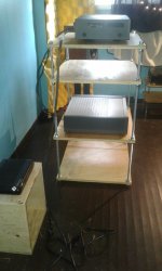
I was saving this nice finish side ply for open baffles. I need to separate my audio pile for better isolation. I wasn't planning to make a flexi design rack this weekend (hence cutting it with a jig on short notice).
Guys its sounded fine this far, going on 72 hours, not a peep.
Funny thing, that old Dewalt out lasted 3 or 4 late models, and still cuts straight.
Guys its sounded fine this far, going on 72 hours, not a peep.
Funny thing, that old Dewalt out lasted 3 or 4 late models, and still cuts straight.
Attachments

Can I confirm that 72 hours running the amplifier with shorted input and no intermittent buzz, but you did once have buzz in the right hand channel when the preamplifier was connected but turned off?
Can I confirm that 72 hours running the amplifier with shorted input and no intermittent buzz, but you did once have buzz in the right hand channel when the preamplifier was connected but turned off?
Yes, I did switch the preamplifier off when I "caught" it buzzing, the buzz continued, ( with only the power amp itself left switched in the 'on' position) connected to L and R speakers. I thought I mentioned that. However I can see how this can get a little confusing to follow at times, with so many mundane but necessary details.
I might of had more fun cutting 10 2'x2' plywood shelves with a jigsaw.
That's what I understood but I just wanted to be sure. The result of those two observations implicates the RCA leads and/or earthing arrangements between the two units. Mooly described a situation he had like this in the post here: https://www.diyaudio.com/community/...-buzzing-from-one-channel.382104/post-6922033
As the problem is manifesting in a power amplifier, it is important that the earthing strategy inside the amplifier is correct. The body of the RCA inputs must be either directly connected to the chassis or at least bypassed by ceramic capacitors. The mains earth (if there is one) should be connected to the chassis as well. There should be only one DC connection between the chassis and the ground of power supplies, either through the RCA ground if not bypassed, or if the RCA screens are bypassed by another cable from the centre (0V) of the power supply capacitors to the electrical ground (preferred).
The loudspeaker grounds should also connect to the centre of the power supply capacitors. This layout prevents the formation of RF sensitive loops inside the amplifier and also ensures the case of the amplifier is an effective screen. (It also prevents voltage drops across "grounds" at different parts of the amplifier due to inadvertent current flow though ground conductors, to keep the ground equipotential throughout the amplifier.) Supply bypass capacitors should ideally connect directly back to the point on the circuit boards where the 0V from the capacitors is connected, however it is likely that these cannot be changed as they are built in to the pcb layout.
If the layout already complies with one of the two layouts suggested above, then check for dry joints on the RCA ground or bypass components in the amplifier. If all of that seems in order, it may be necessary to look at the preamplifier internal grounding.
Last edited:
Having the preamp turned "off" but plugged in is not the same as having shorting plugs in the RCA jacks. The coax wrap of the two RCA cables plus the internal ground of the preamp makes a giant loop to pick up RF & hum.Yes, I did switch the preamplifier off when I "caught" it buzzing, the buzz continued, ( with only the power amp itself left switched in the 'on' position) connected to L and R speakers.
This is a RCA plug https://www.newark.com/switchcraft-conxall/3501mx/rca-connector-plug-2pos-9-1mm/dp/03M4295?st=rca plug
You solder a wire across it, making a very short loop and totally covered by copper. Takes two of them to protect your amp from RF that way.
The preamp, if it has an external wall power supply, may not turn that off anyway when you turn it off. Usually the wall device remains powered. If a switcher, the wall supply can make RF noise. Same with the power supply for a flat screen TV. Those are all switcher supplies, and the switcher never turns off. Only the display.
For finding any internal component in the amp causing the buzzing,
This is an analog voltmeter with a 2.5 20 & 50 VAC scale https://www.newark.com/simpson/12388-260-8/multimeter-analog-6-functions/dp/62F300
You can buy a much cheaper one ($18) with only a 50 vac scale at the local hardware store. You can get ones for about $30 with a 20 VAC scale on ebay. Analog VOM are longer lasting than scopes, no internal electrolytic caps to dry out. My simpson 266-xlpm analog VOM I bought in 1986 still works fine. With analog meter you need a .047 uf 200 v capacitor https://www.newark.com/panasonic/ecqe4473jf/cap-film-pet-0-047uf-400v-radial/dp/62W6564
to block the meter from reading dc voltage on the AC scale. You need a couple of alligator clip leads https://www.newark.com/pomona/6356-24/test-lead-set-609-6mm-70v-5a/dp/94B5529?st=clip lead
which are unfortunately $70 for 10 from newark but $6 for 10 from www. parts-express.com
Don't fall in the trap of "digital is better", most DVM make random numbers testing music with the AC volts scale. RMS DVM make real numbers but ignore any signal over 7000 hz, which amps are prone to produce when they oscillate. My disco mixer oscillated at 1 mhz. An analog VOM will see that.
Or you can buy an oscilloscope https://www.newark.com/multicomp-pro/mp720014-us/handheld-dso-20mhz-rohs-compliant/dp/10AH2397
plus two 10x probes @ $52 each. https://www.newark.com/b-k-precision/pr-37ag/probe/dp/24C6097 Plus a ground probe banana jack to alligator clip for $7. https://www.newark.com/pomona/3220-36-0/test-lead-black-914mm-60v-5a/dp/10M4234
Don't for get the soldering iron and wire for shorting the RCA plug. vari-temp hakka iron is okay from newark or digikey, but the $40 varitemp iron from parts-express.com I have found very useful.
Again, I would find the base lead of the VAS transistor on the buzzing channel a good first place to look to see if the buzzing is before or after. It would be the left lead looking at the numbers of the TO202 transistor (looking like a MJE340). That would cut the problem in two. One problem with this amp, there are no component leads to clip onto, so you have to press a meter probe to the bottom of the pcb the entire time you are listening for the buzzing. Note big pops in the (trash) speaker as you press a solder joint with a meter probe indicates that joint requires resoldering. Trash speakers can be bought at charity resale shops or junkyards. You may need to solder wires to it, and banana plugs if the amp doesn't have binder terminals.
Last edited:
Thanks for the detailed explanation and links.
I will absolutely look at installing some. I have a couple soldering irons and voltage testers, all except an oscilloscope.
The TV posing trouble jogged my memory, rewind about 10 years. I had a Denon AVR 591. When it was playing FM radio when a swung the TV close to it that would cause white noise to interfere with the FM quality, you could here it but you could also hear white noise or "snow".
Flat screens emit some type of field within a certain range of the TV. Possibly this getting too close to the pre/amp caused the amp to pick it up? I can't prove anything but so far since moving the audio a couple feet back and away from, nothing yet.
I have a strong feeling its that, or the path you guys are on. With any luck, because I wasn't able to find a tech to work on ML within a couple thousand KMs. If its beyond my capability.
I feel more confident working in the preamp, it wouldn't be as hard to replace. In my free time I'm going to brush up on my soldering technics. I use to build stain glass and did a fair bit of soldering, some brazing.
These are helpful, they go over curcuits and heat ranges
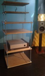
The Salamander clone I banged out to aid with isolating the components just needs bolting together, it turned out fine will show ya, Its all cut and clear coated. That could be my speediest DIY project in history.
I will absolutely look at installing some. I have a couple soldering irons and voltage testers, all except an oscilloscope.
The TV posing trouble jogged my memory, rewind about 10 years. I had a Denon AVR 591. When it was playing FM radio when a swung the TV close to it that would cause white noise to interfere with the FM quality, you could here it but you could also hear white noise or "snow".
Flat screens emit some type of field within a certain range of the TV. Possibly this getting too close to the pre/amp caused the amp to pick it up? I can't prove anything but so far since moving the audio a couple feet back and away from, nothing yet.
I have a strong feeling its that, or the path you guys are on. With any luck, because I wasn't able to find a tech to work on ML within a couple thousand KMs. If its beyond my capability.
I feel more confident working in the preamp, it wouldn't be as hard to replace. In my free time I'm going to brush up on my soldering technics. I use to build stain glass and did a fair bit of soldering, some brazing.
These are helpful, they go over curcuits and heat ranges
The Salamander clone I banged out to aid with isolating the components just needs bolting together, it turned out fine will show ya, Its all cut and clear coated. That could be my speediest DIY project in history.
One cost saving tip, don't buy from Newark.com into Canada unless you can get them to ship USPS. Click that on shipping options if it is available. Sometimes it is not. Royal mail will allow you to pay customs charges at your post office. UPS that newark uses charges a "customs loan fee" that is >$20. If you use digikey.com in Minnesota, they ship across the border into Canada with their own truck and handle the customs themselves.
If you want to watch a point with a meter for days & days, with no leads to clip onto, you can solder a wire to it that goes to the meter lead. Then when you are through with that point, desolder the wire. Don't use a 80 w or 100 w iron on pcb's, it will either cook the component or lift the land off the board. Work fast & use a hot iron. I use a 3 mm chisel tip to speed heating on my parts-express iron, available in a replacement tips kit. I only use the pointed tip the iron ships with on IC leads. The parts-express varitemp iron is 40 watts, but shuts off heat when the tip is up to temperature.
I like newark because 100 resistors from them are a lot cheaper than digikey or mouser. They sell 1% resistors 9% off the EIA 20% value for $1.20 a hundred lots of times. Also newark puts a asterisk and discounts electrolytic capacitors past their shelf life. I recieved a full price e-cap from digikey that was 9 years old. One they reach 10 years, you can't tell: digikey wins. The date code now is only 3 digits, YWW. Electrolytic capacitors past their shelf life have to be charged up to 2 v with the diode scale of the meter (or a battery or power supply) before they are hammered with full voltage. I've never exploded one doing that.
Parts-express uses UPS only, so if you can find a Canadian supplier of 40 w iron (digikey has hakka) and alligator clip leads <$70 for 10, do that & save a UPS customs fee.
As far as the debugging process, we'll help you learn. First isolate the buzz as internal to the amp with the shorting plug & getting it away from the switcher supply appliances. Then if sure it is internal, prove which board the buzz is on with a couple of trash speakers. Trace the wires from the speaker binder posts to the board. Then cut that board in two with tests halfway through. I suggest the base of the VAS. Then if sure it is before VAS (present there) or after (missing there but present in speaker) find another test point that will cut that half in half. Eventually you'll isolate down to one stage, where you'll start pressing everything with meter probe or chopstick. You may be able to increase incidence of buzzes with a hair dryer or circuit cool spray. A bad solder joint could be the cause; also a bad weld inside a component. Resistors are the cheapest components, but capacitors & semiconductors can have bad internal welds, too.
You use the 2.5 vac scale of a meter before the VAS and at the base if it. 20 vac scale collector of VAS & after. 50 vac scale on the driver transistors & output transistors. Note a VOM will kick the pointer as you put the capacitor input onto different DC voltages. This is the capacitor charging up and is not an interesting phenomenon. The speaker may pop when you do that too.
Happy hunting.
Last edited:
I'll be reading that twice with a clear mind over the weekend.
In the mean time I tidied up, no more crates to put electronics. Temporarily or other wise.
Its been ok thus far, knock on wood, no secondary noise occurrences.
Amp fits about as good as I could ask. The shelf being the rush that it was, turned out, will make a good dividing point. Now I have no excuse for messy wire or equipment or stacking or wire bundling. Although I have never stacked, that's a big no no. The whole room needs entire revamp.
Attachments

Last edited:
I haven't been babying the system at all, I even went back and forth a few times with more/less efficient 4 ohm 200w speakers, lots of dynamic clean power, noise free. That's what makes such a thing a chore to catch. Have powered off, an hour sometimes, or less. To cycle heat, testing the best I know how...
- Home
- Amplifiers
- Solid State
- help diagnose power amp buzzing from one channel