Hey everyone,
I'm a newbie in the diy speaker world and I decided to design and build my first speaker set. I was trying put together a two ways bookshelf speaker with the Scan-Speak Discovery D2608/91300 as a tweeter and the Peerless HDS-P830875 as a woofer.
I did some research in order to understand some more about crossovers and tried to design a 2nd order crossover to connect the two pieces together. The only tool I was able to use is Xsim, in order to simulate the crossover behavior.
The frequency response and impedance files were taken through the use of a graph tracer and some photoshop playing, not the best probably, but it is what I can do for now.
In the pictures there is the design I came up with and the frequency response graph together with the impedance graph. Can anybody explain me a little bit better what I am looking for when designing a crossover in a simulator like this one?
In any case I'm asking for suggestions and corrections of any kind, thanks in advance!
The files are attached down below, also the frequency response and impendance of the single drivers
Attachments
-
 Design - Crossover n.1.jpg52.9 KB · Views: 142
 -
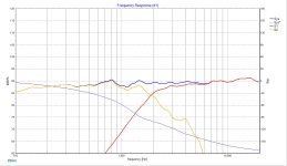 Frequency Response - Crossover n.1.jpg117.2 KB · Views: 131
 -
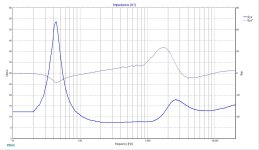 Impedance - Crossover n.1.jpg130.5 KB · Views: 123
 -
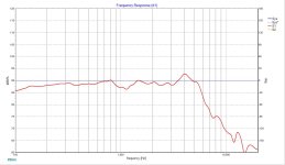 Peerless HDS-P830875 - Frequency Response Picture.jpg109 KB · Views: 125
 -
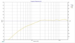 Scan-Speak Discovery D2608-91300 - Frequency Response Picture.jpg104.8 KB · Views: 132
 -
Peerless - HDS-P830875 - FRD - New.FRD9.6 KB · Views: 70
-
Scan-Speak Discovery - d2608-913000 - FRD - New.FRD9.6 KB · Views: 70
-
Crossover design n.1.dxo63.6 KB · Views: 75
You are doing well so far. You could turn off system phase and turn on phase for each band. You could consider the baffle step.
Do you have Microsoft Excel? Have a read of https://sites.google.com/site/undefinition/diy-speaker-faqs/simulated-measurements
He describes how to get a rough (but better than not doing it) idea of the effect of putting the drivers on a cabinet baffle, to make a better simulation.
He describes how to get a rough (but better than not doing it) idea of the effect of putting the drivers on a cabinet baffle, to make a better simulation.
Also, you might like to look at Troels' http://www.troelsgravesen.dk/Peerless_HDS830875.htm which uses the same driver and tweeter, but in 2.5way
By turning on phase for each band what do you mean exactly? Also is it normal to have the system impedance going so high on lower frequencies around 40 hz? It touches 50 ohms on the graph. In general what should I expect from an impedance graph?You are doing well so far. You could turn off system phase and turn on phase for each band. You could consider the baffle step.
If you bring up the box for each trace you can add phase.
Impedance should be what am amplifier can manage. It’s ok for it to vary as long as it doesn’t get too low.
Impedance should be what am amplifier can manage. It’s ok for it to vary as long as it doesn’t get too low.
You can study the Bykron a 2.5 way which uses the same drivers under german names.
https://www.google.com/search?q=nyk...vEpIBBDItMTCYAQCgAQHAAQE&sclient=gws-wiz-serp
https://www.google.com/search?q=nyk...vEpIBBDItMTCYAQCgAQHAAQE&sclient=gws-wiz-serp
or this one to get an idea about the xover of the P830875
https://www.rob-elder.com/LouC/speakers/VP/Veeper.html
https://www.rob-elder.com/LouC/speakers/VP/Veeper.html
Thanks for the articles! The second one, the bookshelf speaker has very interesting information. I was thinking of two ways sealed enclosure, using as internal volume the Vas compliance stated on the woofer spec sheet, which says 21.78 L. Considering the simplicity of a sealed enclosure, does the damping material volume need to be taken into account when calculating the volume for the whole enclosure?
About the baffle equalization, should it happen with a circuit block in the crossover?
Thanks everyone for the suggestions so far!
About the baffle equalization, should it happen with a circuit block in the crossover?
Thanks everyone for the suggestions so far!
Hi,
just for info: crossovers duty extends from splitting the sound to various transducers to EQ, to impedance manipulation even. For this reason, recommended workflow for most accurate results is: one first builds the whole speaker without crossover, then the speaker is measured. The real measurements are then loaded into a crossover simulator, and crossover is fitted to the build you have at your hand.
The physical structure also affects how the speaker sounds, how the sound reflects and diffracts, how the multiple transducers locate to each other and combine. When you measure the complete thing and use the real data of the real deal in the crossover simulator its possible to actually get the crossover (hopefully) as good as it gets. As good as it gets for the given drivers and physical structure, for the measurements you fed into the simulator.
If the end result doesn't quite sound right, assuming the crossover was as good as it gets for the construct, the next step is to build the whole speaker again with possibly different transducers, with their relative position along with size and shape of the structure refined based on the previous experience. Now build the better construct, measure again, fit another crossover, and if this all was done with thought involved you have now better speaker than before.
Making up a crossover with factory data and putting it all together at once and hope for the best, which kind of makes into ballpark, but is far from optimal.
This is not to discourage you but to encourage!😀 Being in ballpark might be your goal. Most important thing is to have fun with the hobby, so progress with path that feels relevant and interesting to you, and have fun!🙂
Last edited:
HAve you chosen the box volume? Do you have experience with software WINISD which is a box volume simulator, You have enter woofer's TS parameters as a new driver because it is not in the drivers list. Then open a new file and load the driver data. The software will give you the choice between vented or closed and suggest a box volume. You can play with the box volume and vent length. As far as I remember the P830875 is suited for Vented, but for closed the low end will be lacking. Next step once you choose the volume, you must work on the box dimensions, I suggest using BOXYCAD, an excel based file. The width of front baffle dimensions will affect baffle step. Follow tmuikku's first paragraph.. build the box, etc.
- Home
- Design & Build
- Software Tools
- Help designing my first crossover