Hello good people,
Need some advice, insight, suggestions and criticism from you. I recently got onto the diy bandwagon after years of being a consumer. Two months ago I successfully built a tda 2030 amplifier 😂, and now I feel that i should join the bigger boys with a discrete AB amp.
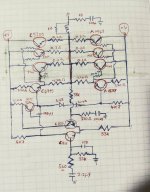
The below is a design 'stolen' from some chinese manufacturer, it's based on c5200 A1943 outputs.
I've tested it using a 20-0-20v transformer and it was kinda working with some problems. I don't have an oscilloscope. Here in Kenya the price of an oscilloscope can feed two villages for a month. (I'm okay with that though)
So, I'm diving blindly into it with just a multimeter ,soldering iron and some poor speaker whose life is on the line.
kindly check out the attached schematics and help answer the following questions.
1. What's the best (maximum and safe) transformer voltage and amps to run it?
2. How many parallel outputs are recommend to get more power and handle 4ohm loads well? And what can be done on the drivers to make them handle more output transistors?
4. Are the biasing resistors values and diodes done well?
5. What are the improvements, corrections, that can be done to make it a better sounding yet powerful amplifier?
I'm very, veeeery new to electronics. Y'all's answers, advice and support is highly requested and appreciated
Best regards
Need some advice, insight, suggestions and criticism from you. I recently got onto the diy bandwagon after years of being a consumer. Two months ago I successfully built a tda 2030 amplifier 😂, and now I feel that i should join the bigger boys with a discrete AB amp.
The below is a design 'stolen' from some chinese manufacturer, it's based on c5200 A1943 outputs.
I've tested it using a 20-0-20v transformer and it was kinda working with some problems. I don't have an oscilloscope. Here in Kenya the price of an oscilloscope can feed two villages for a month. (I'm okay with that though)
So, I'm diving blindly into it with just a multimeter ,soldering iron and some poor speaker whose life is on the line.
kindly check out the attached schematics and help answer the following questions.
1. What's the best (maximum and safe) transformer voltage and amps to run it?
2. How many parallel outputs are recommend to get more power and handle 4ohm loads well? And what can be done on the drivers to make them handle more output transistors?
4. Are the biasing resistors values and diodes done well?
5. What are the improvements, corrections, that can be done to make it a better sounding yet powerful amplifier?
I'm very, veeeery new to electronics. Y'all's answers, advice and support is highly requested and appreciated
Best regards
Attachments
1 Start with relative low supply voltages and notice if this heat up (to) quickly, say +24/-24V.
2 There are already three 5200's and three 1943's in parallel: that's sufficient for 4 ohms.
(3) Not neccessary, the drivers are a load on the MTC350, which is somewhat limited.
4 Resistor values are ok for now, but two diodes are to few. There are four base-emitter junctions in series, so that demands four diodes 1N4148 at least. Better is a proper bias network (rubber zener) with bias adjustment to control the bias current in the 5200/1943 pairs. Add a bootstrap to the 4k7 resistor (split in 2k2 and 2k7) with a cap of 100uF in between to the output (plus on output, minus on the split node).
5 Connect the collector of the C1815 (from the feedback) to the power rail to increase stability. In this way it does hardly increase the open loop gain but makes the circuit more sensitive to oscillation.
Increase the 33k input resistor to 47k and add an extra resistor of 47k on the input side of the 2.2uF input capacitor to ground to avoid loud pops that could destroy your poor speakers.
Compare this circuit with other proven circuits.
Maybe others will contribute usefull improvements too.

Even the amp is designed with symetrical power supply, i would use cap on the output as safety first. Once all is working for days or weeks, its ok to remove it.
You do not need 3 pairs of outputs unless you want to drive low impedance speakers very hard.
You do not need 3 pairs of outputs unless you want to drive low impedance speakers very hard.
There is plenty of well designed verified amplifiers with c5200/a1943 outputs, just search apex audio
https://www.diyaudio.com/community/threads/100w-ultimate-fidelity-amplifier.164093/
https://www.diyaudio.com/community/threads/100w-ultimate-fidelity-amplifier.164093/
In your schematics, there is no dc adjustment, no bias adjustment, so you will have to tweak resistors to get to the optimal operating conditions.
Use just one pair, the populated PCB are sold here in India.
Kenya, just check.
At least it will work, and you will listen to music rather than modifying this endlessly.
Pick your pleasure, modifying or fiddling.
And as Adason says, there are plenty of circuits for that very popular transistor pair. So bias resistors and other values will be part of the diagram.
Search for "5200/1943 amp schematic", most search engines will give too many results.
No need to steal Chinese diagrams.
Are your transistors genuine or fake?
Last edited:
It may depend also on how much your mains voltage varies in Kenya.1. What's the best (maximum and safe) transformer voltage and amps to run it?
How much does it vary in your place?
Anecdotally, too much....grid regulation is poor.
Please recommend the lowest safe and steady voltage for this pair, even we had variation here from 190 to 290 V, full load to no load here in our industrial area.
Lowest, so the amp does not blow when the voltage spikes.
I had to use a voltage controller to protect my equipment.
Please recommend the lowest safe and steady voltage for this pair, even we had variation here from 190 to 290 V, full load to no load here in our industrial area.
Lowest, so the amp does not blow when the voltage spikes.
I had to use a voltage controller to protect my equipment.
5 Connect the collector of the C1815 (from the feedback) to the power rail to increase stability. In this way it does hardly increase the open loop gain but makes the circuit more sensitive to oscillation.
Are you sure about that? It looks to me like a trick to move the right half plane zero further to the right and improve stability.
Normally the compensation capacitor, transconductance of the MTE350 and its 220 ohm emitter resistor (meant for current limiting during clipping?) together set the right half plane zero location, with the special connection you kick the 220 ohm emitter resistor out of the equation.
Is "rubber Zener" another term for an adjustable VBE multiplier?
We get variations between 230-240vIt may depend also on how much your mains voltage varies in Kenya.
How much does it vary in your place?
This is very insightful, thank you very much.
When I tested the circuit, only the VAS mje350 heated, which i assume is normal (ish?)
I'mma update after the modifications
When I tested the circuit, only the VAS mje350 heated, which i assume is normal (ish?)
I'mma update after the modifications
1 Start with relative low supply voltages and notice if this heat up (to) quickly, say +24/-24V.
4 Resistor values are ok for now, but two diodes are to few. There are four base-emitter junctions in series, so that demands four diodes 1N4148 at least. Better is a proper bias network (rubber zener) with bias adjustment to control the bias current in the 5200/1943 pairs. Add a bootstrap to the 4k7 resistor (split in 2k2 and 2k7) with a cap of 100uF in between to the output (plus on output, minus on the split node).
5 Connect the collector of the C1815 (from the feedback) to the power rail to increase stability. In this way it does hardly increase the open loop gain but makes the circuit more sensitive to oscillation.
In well designed amps driving the MTE350 emitter from the nfb side of the diff is ok so the zero becomes more dominant, but unknown for this circuit. Stability issues can arise with the millercap of the C1815 and the Cbe of the MTE (two poles) at HF (often visible in open loop simulation).Are you sure about that? It looks to me like a trick to move the right half plane zero further to the right and improve stability.
Normally the compensation capacitor, transconductance of the MTE350 and its 220 ohm emitter resistor (meant for current limiting during clipping?) together set the right half plane zero location, with the special connection you kick the 220 ohm emitter resistor out of the equation.
Is "rubber Zener" another term for an adjustable VBE multiplier?
It is heating with a 20-0-20 transformer, so thats +24 / -24 supply, about some 5mA, 125 mW.
Really: "...kick the 220 ohm emitter resistor out of the equation..."?
Yes, the Vbe-X circuit. Seems american slang, funny.
I think it removes the 220 ohm from the equation for the right half plane zero, because the extra path cancels the signal current from the first stage that would otherwise flow through the 220 ohm emitter resistor. I have to draw it and write out the equations, though. Chances are I won't find time for that this week.
I understand. It is like a quasi-differential stage. Never realized this.
You may pm me that equation but not neccessary.
You may pm me that equation but not neccessary.
I'm thinking of going with the now-popular honey badger,Use just one pair, the populated PCB are sold here in India.
Kenya, just check.
At least it will work, and you will listen to music rather than modifying this endlessly.
Pick your pleasure, modifying or fiddling.
And as Adason says, there are plenty of circuits for that very popular transistor pair. So bias resistors and other values will be part of the diagram.
Search for "5200/1943 amp schematic", most search engines will give too many results.
No need to steal Chinese diagrams.
Are your transistors genuine or fake?
Getting printed boards here in kenya is hard. Getting PCB printing services is hard and expensive . But I've found that copper etching at home is alright for these THT projects.
As for the transistors, Half are salvaged from ex uk amps, the rest are chinese fakes (costing about $1/transistor).
You do not need 3 pairs of outputs unless you want to drive low impedance speakers very hard.
Say I want more power from the amp when I have a capable power supply, won't they contribute to that?
I see the outputs can at most do 150watts, from my electronically primitive thinking , i assumed more outputs result into more output power
how do commercial amps put out crazy watts like 500watts?
If you want more power, you need +/- 70 volt DC power supply. Beefy transformer too, to provide amperage.
I would advise to use that cap on output as I mentioned, it prevents fireworks in the speaker.
PA amps have multiple outputs because people put often crazy speakers together with low resistance, paralleling speakers...
You can find more here:
https://www.diyaudio.com/community/...3-on-25volt-split-supply.379552/#post-6972725
This is great,If you want more power, you need +/- 70 volt DC power supply. Beefy transformer too, to provide amperage.
I would advise to use that cap on output as I mentioned, it prevents fireworks in the speaker.
A good thread linked there too.
I'm okay with 100-120watts into 4ohms.
Side note: I've experienced better results from two subs running from two separate 80watts channels, as compared to just one similar sub running on 150watts.
Please recommend the o/p capacitor value
- Home
- Amplifiers
- Solid State
- Help a NOOB in the middle of some desert in Africa