Firstly A Happy Thanksgiving to all - I hope it was good.
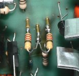
I've got a problem with my newly "repaired" Audire 2 power amp. Long story short: original MPSU07/57's too expensive (and fragile) so I used CEN MPSU07/57's in their heavy duty package on both the original good board as well as the blown board. The specs are the same apart from being able to handle higher current. The 10K 1/2W trimmer pot was blown on the bad board and (using questionable wisdom) I removed the good trimmer pot, measured it out of circuit at 2.46K ohms and made a resistor pair to 2.4K as seen in the photo; the original pot didn't have any series resistor which I'd have thought would have been a good idea and I reckoned that 2x1/2W R's would be a safer bet than a single trimmer - and FYI there is only one trimmer pot on the board. The blown OP transistors (pre suffix G) were changed to a matched pair of MJ15003G/4G from Mouser. These are the only changes to the original that I made.
Now the 'repaired' amp works on both channels BUT (and it's a big but - I'm not shouting) when a signal is input the repaired board and OP's run cold whilst the original once good channel now runs the OP transistors hot enough to fry eggs after only 15 seconds and the transistors and components on the PCB itself stay cold. When there's no signal input everything stays cold. It seems that the OP transistors are now not biased correctly but I don't know what I've done to mess up.
Guys I'm new at this SS circuitry and don't have any gear apart from a DMM. Please tell me how I messed up and better yet please tell me in simple (like ABC) terms how to put it right. I did try a search first as I don't want to hang in like a leech but I just don't know enough to make sense of 90% of the theory and I don't have the schematics for this amp. The DC offset measures -6 to 8 mV on the repaired board and -10 to 12 mV on the original. Please help.
Thanks, Mike.
Attachments
Last edited:
Hi,
I'm assuming that the trimmer is the one that sets the quiescent current in the output stage. This trimmer normally should be adjusted to the output (and sometimes driver) transistors used.
If I understand you correctly you also changed out some transistors in the good channel. That would mean the trimmer is not at the right value anymore, and the quiescent current is too high.
In the repaired channel you replaced the trimmer with the two resistors which again aren't exactly at the right divider ratio but in this case the quiescent current is too low.
In cases like this one would put a multimeter across an emitter resistor in the output stage, measure the DC voltage (which is a measure of the quiescent current) and adjust the trimmer for the correct value.
So in your case, first thing I would do is replace the two resistors with a trimmer that has the same end-to-end value of the original (10k?).
Then you need to find an output stage emitter resistor, put a multimeter across it and adjust the DC voltage such that it carries say 30 mA. It may not be optimal but it will then not blow up and the crossover distortion wont be too bad.
The best is of course to find a service manual and actually adjust as specified.
One final thing to note: before switching on the amp after replacing the trimmer, set it to minimal quiescent current. Almost always that is when you turn it such that the in-circuit end-to-end value is close to zero. That minimizes the Iq and you can then turn it up while measuring the DC drop across that Re.
Hope this is helpful,
jan didden
Have a look at any schematic that shows the output emitter resistors. See they connect the upper emitter to the lower emitter.
There should be one emitter resistor to each output device.
All BJT power devices have bce pin order. The rightmost pin is always Emitter when looking at the package at the labeled face. To220 are the same. To126 are reversed, i.e. ecb.
When you look at your PCB you should be able to see the trace and the emitter resistors that connect the upper emitter PIN to the lower emitter PIN. Those are the emitter resistors that are used to measure the output bias voltage.
Thank you both gentlemen for giving me the details in an easy to understand way. The Audire is a really old amplifier with all of the components except the OP transistors located on two identical PC boards; then there is a 'bunch' of tied together leads (wiring) that travel from the boards to the OP transistors which makes it hard to see which wire connects what to what and also because of their location it's virtually impossible to separate them out to get a better view of the connections.
There are two 0.22 ohms 5 Watt 5% wirewound resistors per board that I assume must be the emiitter resistors since they are the only ones of such low R and high W. These were blown on the board that I repaired if that helps - I believe these may act like a kind of fuse in the OP?
I didn't want to change out the original good transistors but they were very fragile and carried glued-on heatsinks - about 1/2" x 2" of alloy 'wings' that made handling and manipulating the board for desoldering without damaging it impossible for me. The legs on those original transistors were very very thin and snapped off at almost a touch; it's a pity that I had to replace the good ones because of my own lack of handling skills but I did as best I could.
I tried to find a replacement for the original 10K trimmer pot but couldn't find a vertical pot 1/2W like it listed anywhere except one seller in the UK on eBay, and I did try a multiturn Cermet but it was physically too small: do you think it would be okay to use a Cermet with 'extension' legs and (say) epoxy glue to give it some support?
Again many thank you's for your great help that I truly appreciate.
Best regards, Mike.
Last edited:
If the 5W wirewound 0r22 emitter resistors were blown, then there will be much greater damage in the semiconductors around the output stage. The fragile legs of the driver transistors is of no importance. They were almost certainly damaged from that "mishap".
Are the output devices in To3 packages (metal) with 2PINs underneath and no apparent third PIN?
Are the output devices in To3 packages (metal) with 2PINs underneath and no apparent third PIN?
Hello Andrew, and thank you again for your help. I did see that you offer a lot of help and advice here on DIY ... most kind. Yes the output devices are exactly as you describe ... To3 I believe.
It's so odd (at least to me as a newbie oldie) that the amp now works and doesn't sound distorted in any way even though the bias is so far off. However I'm looking forward to getting it right - it's hard work for me, but I do get a lot of satisfaction in trying.
My best, Mike.
It's so odd (at least to me as a newbie oldie) that the amp now works and doesn't sound distorted in any way even though the bias is so far off. However I'm looking forward to getting it right - it's hard work for me, but I do get a lot of satisfaction in trying.
My best, Mike.
Ian Finch can you please contact again please - I received an email from DIYaudio showing your kind reply but it doesn't show up here in the thread.
You asked:
I played it softly at low volume when I tested it. I apologise for my ignorance but I don't understand the quoted words - how could it play without using the main outputs - I'm lost here. Could you elaborate please.
Many thanks, Mike.
You asked:
BTW, just how loud are you playing the amp. when listening? It may not be from the main outputs at all if playing softly.
I played it softly at low volume when I tested it. I apologise for my ignorance but I don't understand the quoted words - how could it play without using the main outputs - I'm lost here. Could you elaborate please.
Many thanks, Mike.
Thanks for chipping in Andrew, it's appreciated.
I see you are listed as living on the Scottish Borders ... may I ask (even approximately) where in the borders you are: I spent some time in the way past days in both Northumberland and Scotland (on the coast of Scotland and in a tiny place in Ayrshire) and have very fond memories of both the places and the people I met.
My best regards, Mike.
Last edited:
Hi Seebert
My post only detailed the TO3 connections which Andrew had already posted but I did not see. I deleted the unnecessary post asking that question, since there was doubt about the rest of the output stage being OK.
A number of faults allow Emitter follower design power amplifiers to pass audio from the preceding driver transistors or earlier in the amplifier through faulty transistors. As the volume is increased, a point sometimes arises when harsh distortion occurs, confirming that not all the silicon is well. Then it's DMM time and first verify all Base-emitter junction voltages as around O.6V. This needs a steady hand, not slipping to short something else into oblivion.
However, as you replaced the output transistors and the DC offset is OK, you have clean sound, then it remains to set the quiescent current as Janneman has suggested then assuming the "cold" amp remains functional as quiescent current warms it a bit, gradually raise the volume to check that the drivers are actually intact. It may seem extravagant, but I would replace drivers regardless in that circumstance as they will certainly have had a rough time and maybe cause havoc sooner than you'd like.
Thank you for the post Ian.
((In the following the capital letters in parantheses are for my benefit - I have to think aloud these days - old age and a dull (or dying) brain - and wish I was joking))
If I initially have the trimmer set to minimum resistance and following Ohm's law (E=IxR) then I can see that the quiescent current (Iq) will be at a minimum with a given voltage applied. Now DMM probes set across one emitter resistor and look for 30mA which to me translates (E=IR) to about 6.5mV or 13mV across both resistors.
From searches on setting bias here on DIYaudio I was left with the understanding that the 'usual' voltage drop across both of the emitter resistors should be about 22mV to balance power output (and best sonics) with reasonable heat dissipation in the OP transistors, with some saying that they go up to 40 or 50mA for 'improved' sonics. I assume this is more into Class A biasing at lower volumes, but that seems like a big value spread to my unqualified mind. I really don't want to see a smoking enclosure ever again (well, one can hope) so could the learned please tell me where I am going wrong with my thinking here?
Thanks to all, Mike.
Hi
You have the right idea there. For transistors generally, there is a base-emitter junction "diode" drop of O.65V approx. to bias, such that no step appears in the transfer of current to a load. In the E-F amplifier here, there is a positive and negative half swing of the output through the transistors which are switched in cycle to the load according to the drive signal. There are 2 series diode drops in each upper and lower half of the output stage and four in total to be forward biased by the bias generator circuit. It requires typically 25mA to bias these four junctions and that is the minimum or "optimum bias" level that can be be further trimmed using a distortion analyser to get lowest distortion for a particular amp.
However, many people disagree that this bias level results in sound as good as with more bias again, thus taking the amplifier closer to class A as you say. Different manufacturers have different ideas of bias level for subjective impressions too, particularly in newer up-market designs. The b-e diode voltage is also strongly temperature dependent so the actual bias applied has to be compensated by a sensor diode/transistor for even fair accuracy. It also happens that many designs are only steady in a particular bias range so it is wise to check bias current once the amp is warmed up and again after the cover has been in place to make sure it has reached a fair working temp.
You may see now that the bias voltage applied to the output stage needs to be reduced by the compenstion as temperature rises, yet the current will be be fairly well maintained whilst thermal runaway is averted.
Generally, at 30mA you have a not uncommon, safe figure. The idea is not to use a level that may drift down 30% to awful low bias nor one that would be considered bad if it drifted up 30%. In the absence of service manuals and specific knowledge of this model's settings, we can only make general but reasonable suggestions. Low bias will only sound bad but high and upward drifting bias is eventually smoke.
Good luck getting it back in shape - nearly there!
A little more help please before I go totally insane !! Okay, I've replaced the 10K pot in the original good circuit (I'm still waiting for the a delivery to do the other channel) and tried to set the bias BUT it just keeps on climbing and climbing and doesn't stabilise. I have since checked and rechecked every component and cannot find anything amiss: all values are seemingly correct. One 19K resistor from the rail down to the collector of a 2N5961 which then feeds to a SU57 driver then on through "xxxxxxx2N5961 etc" gets very hot but every component in the "xxxxxxx2N5961 etc" chain checks out okay. I know all this is VERY vague - sorry as yet I haven't been able to draw out (decipher) the circuit - but from this small amount of rank amateur info can someone please give me an idea of what kind of component faults would cause a continual rise in bias current. It starts out at 4mV and rises by 1mV every two seconds - I haven't let it go over 40mV before disconnecting. Again, every component checks out as okay on my DMM and any idea of how to proceed would be very (very) welcome. Should I have 'sacrificial' speakers connected? Right now I'm running with no load connected to the speaker outputs.
BTW if I blow (a lot) on the components that get hot the rate of voltage rise measured across the emitter resistors is markedly reduced.
Many thanks as always for your forebearance, Mike.
BTW if I blow (a lot) on the components that get hot the rate of voltage rise measured across the emitter resistors is markedly reduced.
Many thanks as always for your forebearance, Mike.
Last edited:
Sorry for the dumbo posts - I should have known my limitations both physical and mental. Smoked the new board, took it out, tried running the amp with one board and nothing out at all - zero sound. Great bias though 🙂
Best regards to all and have a happy Christmas,
Mike.
Best regards to all and have a happy Christmas,
Mike.
Last Try To Set Bias (found one blown driver transistor but no other faults) - please help me out on the INITIAL SETTING for the bias trimmer pot so that hopefully I don't end up burning components yet again at switch on :
But, from http://sound.westhost.com/project3a.htm Rod Elliott's page on setting bias :
So help me out here please - do I set the trimmer to minimum or maximum resistance between the outer legs before switch on.
Many thanks, Mike. (I don't know when to give up do I)
From an earlier post by Janneman: One final thing to note: before switching on the amp after replacing the trimmer, set it to minimal quiescent current. Almost always that is when you turn it such that the in-circuit end-to-end value is close to zero. That minimizes the Iq and you can then turn it up while measuring the DC drop across that Re.
But, from http://sound.westhost.com/project3a.htm Rod Elliott's page on setting bias :
Before applying power, make sure that VR1 is set to maximum resistance to get minimum quiescent current. This is very important, as if set to minimum resistance, the quiescent current will be very high indeed (almost certainly enough to blow the output transistors!).
So help me out here please - do I set the trimmer to minimum or maximum resistance between the outer legs before switch on.
Many thanks, Mike. (I don't know when to give up do I)
The more resistance, the more voltage drop over the variable resistor. When it reaches approximately 0.65v that transistor across it will open and 'pull together' the bases of the output transistors, thus reducing the quiescent current of the output stage. You just have to make sure that when you design your own pcb, you pay close attention to the trimmer terminals so turning it results in a clockwise increase of quiscent current (reducing resistance between terminals) where the left most position is no quiescent 🙂
Thanks MagicBox but as is very obvious I'm a rank beginner at DIY audio. I started this repair out of desperation - it was a fried board that in my innocence 'just wanted' to get going again without having adequate knowledge. I replaced all the U/S components and tried once to set bias and poof ... it was history again. I don't have (nobody has it seems) the schematic for it and cannot draw it out from looking at the PCB. Unlike newer designs there are 10 wires that lead from the PCB to the OP transistors and they are (literally) buried in such a way that to unravel them would be (for me) a nightmare of impossibility, so I don't know what on the PCB leads to where after leaving the PCB - if you get what I mean.
I have again measured the boards and replaced one driver MPSU57 transistor and both boards measure roughly the same on everything I can measure on my DMM using diode and Ohms settings.
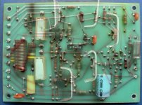
I'm reposting the pic I took a while ago where I imaged the component side over the track side of the PCB: can anyone read this pic and tell me which way to turn the only trimmer pot on the board before I switch on?
Would it be reasonably safe to turn the pot to a midway position as a rough start?
As I've admitted openly I took on more than I should have done and really would just like to get the amp running again - and believe me I'll be reading / taking a course on audio amp (and other) electronics principles and practice beore I (stupidly) over reach my capabilities again in the future.
Thanks, Mike.
I have again measured the boards and replaced one driver MPSU57 transistor and both boards measure roughly the same on everything I can measure on my DMM using diode and Ohms settings.
I'm reposting the pic I took a while ago where I imaged the component side over the track side of the PCB: can anyone read this pic and tell me which way to turn the only trimmer pot on the board before I switch on?
Would it be reasonably safe to turn the pot to a midway position as a rough start?
As I've admitted openly I took on more than I should have done and really would just like to get the amp running again - and believe me I'll be reading / taking a course on audio amp (and other) electronics principles and practice beore I (stupidly) over reach my capabilities again in the future.
Thanks, Mike.
Attachments
Hi Seebert,
We can only assume The circuit Janneman refers to differs to Rod's. We don't know your circuit either, for that matter, so the answer comes from knowing that you have adjusted something like the good channel amplifier already, I assume, and you may recall which way is more and which is less current (read as mV across Re).
You did tell us how you replaced a pot with fixed resistors, no? So you have checked out what resistance it was originally set at and therefore this will be a fairly safe starting point. Why not try this,checking which way decreases current ASAP - but take it steady, no knee-jerk actions sending it the wrong way etc.
Hello Ian, thanks for coming back. I did use a total fixed resistance of 2K2 (that is 2.2K right?) with the idea that I could alter one of the two 'bridging resistors' later as needed since I've read where some re-builders have replaced a variable R with a fixed one. Bad idea - at least for me. The problem is that the bias current (with the fixed R2.2K) was not steady at all - it just kept on rising by the second and would have gone poof so I went back to the one good 10K variable pot that I had left, put it in place of the fixed R and tried to alter the bias again but one touch of the pot (and I do mean just a touch of a turn) and the board went poof again 🙁 OK, so I wasn't going to even attempt more work on it until I got more know-how, but it was just sitting there and well ... I had to go at it and found one bad driver transistor but that's all. The OP transistors were all (strangely ?) okay. Now I've put in a brand new 10K trimmer pot from Mouser and rechecked everything but dare not switch it on. Could it / will it be safe with an initial setting of 2.2K for the pot - I just don't know. On the last atempt at 2.2K one PCB and O/P's were cold and the other channel the blown driver, one reisitor and the O/P transistors got mighty hot very quickly. Question is do I start at that 2.2K or could less - or more R be better ... a question that seems to be impossible to answer without the schematic. Oh for a variac !!!
Try it and be damned ... well it's looking that way isn't it. Or wait until I have a variac. Or the light bulb in the AC supply line might be good - does it work?
The good news is that we might be totally broke here (not by discretional spending on holiday gifts - none this year for anyone I'm afraid - we're just paying our way) but unlike some unfortunate souls have a roof over our head and an internet connection. We do count our blessings.
Best regards, Mike.
Sorry I cannot recall which way I turned the pot last time ... I tried to remember, but the memory is gone.
Last edited:
Yes, the light bulb (if you can still get incandescent ones in your area) is the way to go - simple and so helpful an indication of current draw - which should be minimal for this type of amplifier. If a 75Wbulb (say) glows, you still have troubles. The last resort is to wire 100R 1/4 W resistors across the fuseholders and just protect each amp from DC (fuses removed)
This is not always effective but mostly helps as you can monitor current as the voltage across them. Just be very careful insulating the mains wiring if you go for the bulb protection, by retaining the earth connection to the amplifier. We'd like you to stay around a little longer.
This is not always effective but mostly helps as you can monitor current as the voltage across them. Just be very careful insulating the mains wiring if you go for the bulb protection, by retaining the earth connection to the amplifier. We'd like you to stay around a little longer.
Last edited:
- Status
- Not open for further replies.
- Home
- Amplifiers
- Solid State
- Help A Dummy: in simple language please.