Hi guys, I need your help!
years ago I made a jelabs 300B se amp, which worked well, but with a bit of hum.
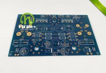
So recently , seen the cost of it, I bought a chinese pcb of a similar schematic, to rebuild mine on a neater layout.
I'm sure you know what pcb I'm talking about, it is shown in the picture attached.
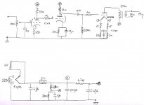
The schematic provided was completely useless, so I ran trough the traces and the real one is attached as well.
Now the problem I am facing is that I have the cathode resistors overheating. If I measure the voltage on the parallel 2k+2k is over 200V!!!
Obviously no sound out of it!
Do you have any idea of what may be wrong with that???
Thank you for any help or suggestion!
Cheers,
Antonio
years ago I made a jelabs 300B se amp, which worked well, but with a bit of hum.
So recently , seen the cost of it, I bought a chinese pcb of a similar schematic, to rebuild mine on a neater layout.
I'm sure you know what pcb I'm talking about, it is shown in the picture attached.
The schematic provided was completely useless, so I ran trough the traces and the real one is attached as well.
Now the problem I am facing is that I have the cathode resistors overheating. If I measure the voltage on the parallel 2k+2k is over 200V!!!
Obviously no sound out of it!
Do you have any idea of what may be wrong with that???
Thank you for any help or suggestion!
Cheers,
Antonio
Attachments
Do you have the 300Bs installed properly (both the tubes and the sockets)? If you install them off 90 degrees, you can short B+ to the cathode bias resistors, then you will get 200V there and no sound out. You'll also destroy the 300B in the process.
audiowise's idea is the most likely cause of the problem.
Other (long shot) items:
Leaky coupling cap (must be rated for 600V or 630V)
Open 300B grid resistor (or bad solder joint)
Open 300B grid stopper resistor (or bad solder joint)
Shorted 300B (mechanical shock when dropped, breaking the filament and a loose filament end is connecting to the plate)
Mis-wired circuit.
Short from B+ supply to 300B filament supply (be sure to use different 5V windings).
Your schematic does not show the filament supply; and it does not show where the A+ voltage comes from.
Hopefully your power transformer, rectifier tube, choke, and 300B all survived. 200V / 1000 Ohms = 200mA.
Possibly OK of you turned the amp off quickly.
Last edited:
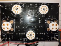
I've made that amp. Never worked well, so I found a newer version of that pcb. It's the same size but with a different layout. Still cheap and sounds great. I put two 1.8K cathode resistors
I also put together this pcb, pretty much worked well, but the hum level was a little high due to the simplistic filament circuit. The schematic provided was not correct, totally different. spent a week tracing the tracks on the pcb was was difficult for a newbie. also a number of parts were not included or were wrong. Douk audio on ebay sold one with better regulation of the filament supply. There’s a youtube video by the @theoldgit aka Peter Doxat of his build of the Douk audio pcb.
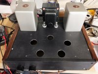
If you search this diyaudio site, there was another guy who did a successful build of the pcb under discussion. I eventually sold the pcb and did a point to point version using a different se circuit from diyaudioprojects. 300b SE. I love the sound of this amp. seems to sound best with my fullrange dayton audio diy speakers ps180-8 although a little more bass freq from a larger cabinet would be ideal.
If you search this diyaudio site, there was another guy who did a successful build of the pcb under discussion. I eventually sold the pcb and did a point to point version using a different se circuit from diyaudioprojects. 300b SE. I love the sound of this amp. seems to sound best with my fullrange dayton audio diy speakers ps180-8 although a little more bass freq from a larger cabinet would be ideal.
Last edited:
Thanks guys,
unfortunately there seems to be none of the issues suggested.
The triode socket is correctly placed and the tubes lit up correctly.
Maybe my 300Bs are just gone. Any way to check them?
What about plugging in just the rectifier and check the voltages around?
If there is something wrong with the wiring I should already see HV on the cathode resistors... maybe...
I will look for the others pcbs suggested, thanks!
Check continuity of the 300B grid circuit to ground (measure the resistance), then measure the grid voltage when powered - it should be pretty close to 0V. If not coupling caps or grid resistor arrange is suspect.
Check continuity of the 300B grid circuit to ground (measure the resistance), then measure the grid voltage when powered - it should be pretty close to 0V. If not coupling caps or grid resistor arrange is suspect.
300B grid to ground measures around 220K...
Bummer! powering with only the rectifier on board, the two parallel 2k overheat even without the 300B connected... odd.
Better removing all the capacitors and check everything...
I think you need to measure the resistance between those resistors and the power supply, I think you may have a short somewhere in the PCB board.
Not really necessary to remove any capacitors I think unless they are covering something you need to see.
Not really necessary to remove any capacitors I think unless they are covering something you need to see.
thanks, yes, I will measure it carefully.
I can see some hundered kohms between the inductance and the 2k resistors, it should be completely disconnected..
I can see some hundered kohms between the inductance and the 2k resistors, it should be completely disconnected..
I would post the clearest possible photos you can of both sides of the PC boards.
With no 300Bs installed, the 2K cathode resistors should not heat up at all.
With no 300Bs installed, the 2K cathode resistors should not heat up at all.
when i had mine i took the following voltage measurements, some i had trouble with at the time.
as follows - left, right
6sn7 (1) grid to cathode 0v,0v ?, plate to cathode 72, 76v, across 750 cathode R 2v, ?
6sn7 (2) grid to cathode 72.1, 75.8 v, plate to cathode 232, 226v, across 15k cathode R 77, 79.4
300b grid to cathode, 55-60v, 56-61v (pin 1-pin 4), across cathode R group 56.5, 61.5v
300b, plate to cathode/heater 306-302v, 307-302v, plate to across cathode R group 365, 365v
As i hear a little hum in both channels i measured about 3 mV across left/right speaker outputs.
After the amp is off, and the B+ is fully discharged:
There should be a fairly high resistance between the B+ choke and the tops of the 2k 300B resistors.
That is because both the bleeder resistors that connect to the choke, and the 2k resistors connect to ground.
But when you first connect the ohmmeter, the resistance should be low momentarily, until the B+ capacitors charge from the ohmmeter.
Last edited:
Is it possible you swapped the primary and secondary connections of the output transformer?
8 Ohms and common connected to 300B plate and B+.
3.5k leads to the 8 Ohm and common speaker connector terminals?
Uh! That's a good point. Would that explain it? I will check!
Sorry, I changed my post # 14.
Part of the problem may be the transformer windings swap.
But some of your symptoms seem confusing, because they do not seem to logically make sense with each other.
Part of the problem may be the transformer windings swap.
But some of your symptoms seem confusing, because they do not seem to logically make sense with each other.
Sorry I misread your previous post. I did definitely not swap 3k5 with the output. I may have grounded the wrong end of the 8 ohm side of the output transformer..
Are you using the same 5V filament winding for the 300B and the rectifier?
You can not do that.
That would put B+ voltage across the two 15 Ohm and the two 2K resistors; and B+ voltage would be much lower than expected.
You still have not shown the schematic for the 300B filament supply.
Swapping the 2 primary leads with each other only reverses the phase.
Swapping the 2 secondary leads with each other only reverses the phase.
Doing both of the above at the same time brings the signal back in phase.
If only one of those is true, and the amp is otherwise working, you would not notice that the phase is reversed.
A pair of amplifiers, one phase reversed, and the other not, would cancel the bass and put the stereo image beyond the 2 speakers (wider than the 2 speaker spacing).
Last edited:
The 5V for the 300B has simply a bridge rectifier with a 10000uF, 16V cap.
and yes, you are correct! I picked the same winding on the power transformer!
and yes, you are correct! I picked the same winding on the power transformer!
Attachments


- Home
- Amplifiers
- Tubes / Valves
- Help 300B se pcb