hi everybody (also quite new to the site)
if i make a speaker enclosure larger in volume than recommended, can i use polyfill to make it correct ?
gaz
if i make a speaker enclosure larger in volume than recommended, can i use polyfill to make it correct ?
gaz
I assume you mean by pollyfill polyester fibres? If so then NO. That will actually increase the effective volume of the enclosure. Counter intuitive I know but it is the way it works.
You would need to use something that takes up volume but won't vibrate or rattle.
Tony.
You would need to use something that takes up volume but won't vibrate or rattle.
Tony.
Yes on a tweeter the resistor in the zobel should never be less than the minimum impedance you want the amplifier to see.
Tony.
I'm not convinced of that actually, i did it many times with success like this. But i won't go in that discussion now. I did make an adaptation of my version, replaced the zorbel with an Lpad and adapted the rest if you like that more...
Attachments
Last edited:
The problem is that at frequencies higher than the cutoff frequency of the cap there is a very low impedance (390 mili ohm) path direct to ground. The amplifier will see this as almost a direct short for all frequencies above this cutoff point.
Your amp may handle it without any noticeable problems but many likely wont.
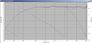
Think about what the cap does. It allows high frequencies to pass. It will present an easier path to ground than the impedance that the voice coil presents and will effectively short the voice coil of the tweeter at frequencies above the cutoff frequency. I wasn't sure what that would be due to the voice coil of the tweeter in the equation so simulated in speakerworkshop with tweeter impedance and frequency extended to 60khz. Attached is the graph.
The impedance the amp would see at 60Khz is approx 1.4 ohms (which is admitedly better than I expected). The glitch in the impedance around 24Khz is because of an artifact in the tweeter impedance curve due to me extending it.
Tony.
Your amp may handle it without any noticeable problems but many likely wont.
Think about what the cap does. It allows high frequencies to pass. It will present an easier path to ground than the impedance that the voice coil presents and will effectively short the voice coil of the tweeter at frequencies above the cutoff frequency. I wasn't sure what that would be due to the voice coil of the tweeter in the equation so simulated in speakerworkshop with tweeter impedance and frequency extended to 60khz. Attached is the graph.
The impedance the amp would see at 60Khz is approx 1.4 ohms (which is admitedly better than I expected). The glitch in the impedance around 24Khz is because of an artifact in the tweeter impedance curve due to me extending it.
Tony.
Attachments

hi everybody (also quite new to the site)
if i make a speaker enclosure larger in volume than recommended, can i use polyfill to make it correct ?
gaz
What i did once, was making a floorstander a bit taller by adding a segment on the bottom filled with river sand and sealed it. It works as a damper on the box, and allowed 30cm taller speakers with the same inside volume. Basicly integrate your sand filled stand in the speaker. But it makes it very heavy (wich is the damping factor)
I'm not convinced of that actually, i did it many times with success like this. But i won't go in that discussion now. I did make an adaptation of my version, replaced the zorbel with an Lpad and adapted the rest if you like that more...
HI Waxx,
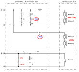
So the components have arrived and I've done a preliminary wire-up and test. Its working but I'm not entirely sure if my wiring is optimal! I've attached a photo - I'm sure there are too many wires and a way of simplifying it but not sure. Any help much appreciated.


Thanks
Jon
Be careful with bare wires and any possibility of an accidental short.
Brass woodwork chipboard screws could be used to secure the vertical inductor cores. Check that the brass screws are in fact brass with a magnet, before using them to anchor the coils.
Hotmelt glue can be used to anchor resistors, I am not so keen on using it on expensive plastic capacitors until 100% sure over thee design.
Old wire insulation, heat shrink tubing or even electrical tape can be strategically placed to stop wires touching. Ideally, other grown adults, children and teenagers need to be supervised and should not be running around too much, the same for dogs, cats and tropical fish. somebody tripping over a wire could short your amplifier, Ideally a test amplifier should have a good output protection scheme.
Others have highlighted possible concerns over impedance at higher frequencies, this does need to be considered.
The circuit is different from the ones at post 32 and 38? Is this a new iteration, should C5 parallel with the tweeter not have a resistor to keep it company at least, or should C5 in fact be a resistor.
Last edited:
Thanks RaymondJ. Your right! Not sure where that change came from - was aiming for design in #36 - I had adjusted for time alignment and that's probably where it came from. I haven't fixed or glued yet as very much in the testing phase. Overall sound is good, a bit bright and I'm getting low level interference so will sheath the bare wires and change the c5 /resistor bit. I feel like I need to try and rearrange the components to reduce number / length of connectorsBe careful with bare wires and any possibility of an accidental short.
Brass woodwork chipboard screws could be used to secure the vertical inductor cores. Check that the brass screws are in fact brass with a magnet, before using them to anchor the coils.
Hotmelt glue can be used to anchor resistors, I am not so keen on using it on expensive plastic capacitors until 100% sure over thee design.
Old wire insulation, heat shrink tubing or even electrical tape can be strategically placed to stop wires touching. Ideally, other grown adults, children and teenagers need to be supervised and should not be running around too much, the same for dogs, cats and tropical fish. somebody tripping over a wire could short your amplifier, Ideally a test amplifier should have a good output protection scheme.
Others have highlighted possible concerns over impedance at higher frequencies, this does need to be considered.
The circuit is different from the ones at post 32 and 38? Is this a new iteration, should C5 parallel with the tweeter not have a resistor to keep it company at least, or should C5 in fact be a resistor.
Your crossover does need a few square cm's to fit it all in that's for sure.
Once you are happy it can be tidied up.
Have you seen how Mr Troels Gravesen lays out his crossovers he uses a tagstrip which you can get from the usual suppliers.
Failing that 1mm or bigger solid single core cooker cable once bent to shape can make busbars anchored around screws in the base board. Maybe you could arrange the negative return onto one main connection strip to give you a star point. Although not absolutely essential right now.
Your point about interference is interesting, is this something you have heard before, or is it new to this speaker configuration?
Stay safe.
Johnny, I'm not seeing it for R1 and C6. The turnover frequency for one thing.
This is why I had to start laying the cables around my fish tank 😉and tropical fish. somebody tripping over a wire could short your amplifier,
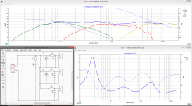
I've done a sim of just the tweeter and mid in speaker workshop. Note I have no information about the baffle or positioning, so have just done a straight comparison of the circuit provided with no driver offsets whatsoever (just min phase drivers and impedance)
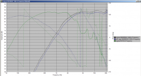
This is to basically show the difference between the two circuits.
By changing the 1.5 ohm resistor to a 3 ohm resistor, and changing the 2.2uF shunt cap to a 20 ohm resistor, the original rolloff can be maintained, with an approx 3db decrease in output, providing what looks like a quite a bit flatter response (blue curve in the third is with the lpad). This will also be much safer for amplifiers.
Note I did not put in the 56 ohm resistor and 100uF cap as they have zero effect on the modeling of the tweeter and mid. Maybe they have some effect on the woofer but to be honest I can't tell what they are for, as they are before any crossover components..
There is a bit of hump in the midrange, but that would require further modifications to get rid of. I would also suggest that without incorporating baffle diffraction effects and putting in all driver ofsets, it would be a bit pointless trying to optimize what I have shown anyway.
Tony.
Attachments
Last edited:
Yes I simmed it yesterday, but since JE had already bought the components.. In my humble opinion it is not unusual that a collaborative crossover couldn't use a little tweak after listening, so perhaps should be expected. 🙂
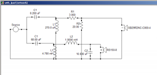
Regarding the 56ohm and 100u. They won't necessarily affect the driver response. The resistor could conceivably improve the relationship between the speaker and (some) amp(s) by reducing impedance variations. That said, in cases where it would, it is better to be frequency specific (ie: the attached image is an example).
In this case, the capacitor is probably pointless as it turns over below 30Hz. Personally I'd either remove the resistor or replace it with a frequency specific conjugate.
Attachments
- Home
- Loudspeakers
- Multi-Way
- Hello. I'm, looking for advice on new 3-way speaker build.