Thanks - I thought that the drivers should have the same power rating, but it seems this is not the case as different drivers draw different levels. Every days a school day! Thank you. The overall power I'm after is really about loudness, I want the speaker to be able to reach house party levels, but also be able to reproduce music to audiophile quality (as much as possible given limited budget!). That's why I've tried to keep speaker efficiency in mind in the driver selection.What does it mean "powerful"? I consider powerful anything in the 50 W range (woofer) 30 W (midrange) and 10 W for tweeter. Passive crossover " eats" some power but instead of having a 20 W amplifier you'll be ok with a 21 W amplifier 😛
Thanks - so do I assume the tweeter is zero, or take measurements from the back of the tweeter to voice coil or mid and Woofer? Or take measurements from the back of the tweeter to back of magnet on mid and woofer. If Tweeter zero, then voice coil of mid is 42mm and woofer is 60mm. Its TMW alignment. The woofer is 15in / 38cm from the tweeter. Mid is right underneath the tweeter (2cm)Xsim allows you to enter offsets. We usually take the top of the voice coil as the offset distance, assuming tweeter is listening axis. For woofer on top alignments we use 0 offset if woofer is the listening axis.
Hi Jon, if you use a high pass filter at around 200Hz and limit your voltage to aroubd 2.8V for your tweeter measurement (the software should have an option to do this) you should be fine. The other two drivers you can sweep from 20 Hz without issue.
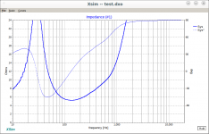
I'm still suspicious about your impedance curves. The 33uf cap on the tweeter (and 0.18 uH shunt coil) seem way off to me, even at the low crossover frequency you have... When you did the trace, did you set the Log/linear option correctly? Some graphs have a linear scale for ohms and some it is logarithmic.
Tony.
Last edited:
Thanks - so do I assume the tweeter is zero, or take measurements from the back of the tweeter to voice coil or mid and Woofer? Or take measurements from the back of the tweeter to back of magnet on mid and woofer. If Tweeter zero, then voice coil of mid is 42mm and woofer is 60mm. Its TMW alignment. The woofer is 15in / 38cm from the tweeter. Mid is right underneath the tweeter (2cm)
Tweeter is assumed to be at 0 Z-offset (domes and ring radiators only).
For cone drivers the offset is the distance between the center of the frame thickness and the top of the voice coil. Usually to the joint between the dustcap and the cone (this may vary depending on cone profile, dustcap/phase plug etc).
The offset you refer to is the Y-offset, which is also good to have.
Thanks will double checkHi Jon, if you use a high pass filter at around 200Hz and limit your voltage to aroubd 2.8V for your tweeter measurement (the software should have an option to do this) you should be fine. The other two drivers you can sweep from 20 Hz without issue.
I'm still suspicious about your impedance curves. The 33uf cap on the tweeter (and 0.18 uH shunt coil) seem way off to me, even at the low crossover frequency you have... When you did the trace, did you set the Log/linear option correctly? Some graphs have a linear scale for ohms and some it is logarithmic.
Tony.
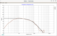
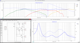
i thought it would be wrong also, so i did a little sim and saw that your FRD and ZMA files are wrong (especially the tweeter). So i did recreate them from specs and the dayton website and did a quick sim. included is the whole project...
Attachments
Also which scanspeak tweeter is it? D or R?
waxx's impedance curve above seems dangerously low above 2Khz!! I found the R2604/8320 which does seem to have a very low impedance looking at the spec sheet, I wonder if the spec sheet is in fact correct?
Tony.
waxx's impedance curve above seems dangerously low above 2Khz!! I found the R2604/8320 which does seem to have a very low impedance looking at the spec sheet, I wonder if the spec sheet is in fact correct?
Tony.
I wouldn't connect that speaker to any of my amplifiers. You expect rising impedance at HF or at least flattish, and above 4 ohms at least.
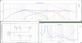
About the convenience of the 3.5 way architecture. When two woofers are used, it becomes possible to create a straight crossover/flat response using one of the woofers, and then to later lay the other woofer upon this using a single order rolloff around the baffle frequency. This later part could even be done by ear.
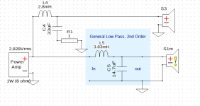
When simulating, it can help to set up a target response as shown below (S1m is the target here and S3 is the crossed driver. LR2@670Hz in this case, but this result is very close to several other rolloff options). This tends to reduce unexpected effects.
When simulating, it can help to set up a target response as shown below (S1m is the target here and S3 is the crossed driver. LR2@670Hz in this case, but this result is very close to several other rolloff options). This tends to reduce unexpected effects.
Attachments
Also which scanspeak tweeter is it? D or R?
waxx's impedance curve above seems dangerously low above 2Khz!! I found the R2604/8320 which does seem to have a very low impedance looking at the spec sheet, I wonder if the spec sheet is in fact correct?
Tony.
That is the point i wanted to make, that tweeter is on the published specs not fit for this. I think the specs are not right.
But to play it safe, i would chnage the tweeter to something that is more in line with logic and fits this system. Something like a Dayton Audio DSN25F-4 is not that expensive and will fit the system when crossed over at 3K
Thanks again Waxx and Tony. before I saw the recommendation I changed the tweeter and the mid-bass. So 3-way nowThat is the point i wanted to make, that tweeter is on the published specs not fit for this. I think the specs are not right.
But to play it safe, i would chnage the tweeter to something that is more in line with logic and fits this system. Something like a Dayton Audio DSN25F-4 is not that expensive and will fit the system when crossed over at 3K
SB Accoustics SB29RDNC C000 4 (4ohm)
Dayton Audio RS150-8 (6") (8ohm)
Dayton Audio RS270P-4A (4ohm)
I got the frd and ZMA from Dayton and traced the SB Acoustics. (and checked this time they matched the spec sheet 😉
So xsim now looks like below.

The Impedence for the tweeter still looks low, but not sure if this is more to do with my crossover design. Thanks again to both of you for your help.
That looks a lot better, but i don't like those resistors in serie with the speakers, better replace those by an L-pad. If you send me the FRD and ZMA files of the tweeter, i can take a go at it to show how i would do it (the rest i have on my computer).
.
Thanks very much for your help - I really appreciate it. Files below
View attachment SBA29R-frd.txt
View attachment SBA29RLin-zma.txt
That looks a lot better, but i don't like those resistors in serie with the speakers, better replace those by an L-pad. If you send me the FRD and ZMA files of the tweeter, i can take a go at it to show how i would do it (the rest i have on my computer).
Thanks very much for your help - I really appreciate it. Files below
View attachment SBA29R-frd.txt
View attachment SBA29RLin-zma.txt
I know that this is theoretical until I buy the drivers and measure them on a test baffle, but essentially want to know if the three drivers I have chosen will work together. The xover design as a beginner to what is a fascinating obsession should be taken with more than a pinch of salt! I've lots to learn - so I really appreciate all the help I can getThat looks a lot better, but i don't like those resistors in serie with the speakers, better replace those by an L-pad. If you send me the FRD and ZMA files of the tweeter, i can take a go at it to show how i would do it (the rest i have on my computer).
Many thanks
Jon
I know that this is theoretical until I buy the drivers and measure them on a test baffle, but essentially want to know if the three drivers I have chosen will work together. The xover design as a beginner to what is a fascinating obsession should be taken with more than a pinch of salt! I've lots to learn - so I really appreciate all the help I can get
Many thanks
Jon
Not only for beginners, i like to design those and mess arround with it. And the more you try, the more you learn how it works.
This is my take, I did not replace the resistors with lpads, but with 2 zorbels, because that works better in this case.
Attachments
Last edited:
Xsim won't show you the load your amplifier sees at higher frequencies. I'm referring to the RC branch near the tweeter.
Xsim won't show you the load your amplifier sees at higher frequencies. I'm referring to the RC branch near the tweeter.
It does, this is it witouth the RC (Zorbel) network...
Attachments
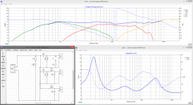
Yes on a tweeter the resistor in the zobel should never be less than the minimum impedance you want the amplifier to see.
Tony.
Tony.
- Home
- Loudspeakers
- Multi-Way
- Hello. I'm, looking for advice on new 3-way speaker build.