I got pretty stuck on this.
Managed to calculate the power dissipation in the circuit and came to a thermal resistance figure (C/W).
Now wtf to do with the C/W unit?
Isn't there some practical way to estimate heatsink dimensions by the power dissipation?
F.ex.
Here are some heatsinks at home:
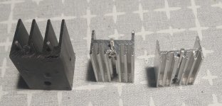
25 х16.5 х16 mm - black one
20.5 х15 х10.5 mm - mid
20 х14.5 х9.5 mm - leftmost
Would the black one handle 4W and how much the smaller ones would handle?
Another one - 50 x124 x35 mm

How much power dissipation for this one?
Regards - Emil 🙂
Managed to calculate the power dissipation in the circuit and came to a thermal resistance figure (C/W).
Now wtf to do with the C/W unit?
Isn't there some practical way to estimate heatsink dimensions by the power dissipation?
F.ex.
- a heatsink for 4W power dissipation, no thermal pad
- a heatsink for 20W dissipation, with thermal pad
Here are some heatsinks at home:

25 х16.5 х16 mm - black one
20.5 х15 х10.5 mm - mid
20 х14.5 х9.5 mm - leftmost
Would the black one handle 4W and how much the smaller ones would handle?
Another one - 50 x124 x35 mm

How much power dissipation for this one?
Regards - Emil 🙂
Thx 🙂, but airflow rate is confusing.
No fan, no airflow, just heatsink.
One of the heatsinks (4-5w power) is going to be inside the enclosure
No fan, no airflow, just heatsink.
One of the heatsinks (4-5w power) is going to be inside the enclosure
Free air convection is the norm, unless stated otherwise.
Maybe using a thermocouple would be easier.
Maybe using a thermocouple would be easier.
When I did automated testing for the server thermal group, they used to put power into the heatsinks under closed loop control, then read back the settled temperature. If the power was off by a bit, they'd just linearly interpolate the temperature rise. This was with airflow in a mockup enclosure / PCB with the heatsinks placed where they were anticipated to land during PCB layout. Things could be moved about if need be at that stage of the design and any position recommendations fed back to the board layout team.
They made use of the stick-on resistive foil heaters in many cases. So you can determine your HS sufficiency empirically. You'll need to measure temperature, current and voltage drop.
They made use of the stick-on resistive foil heaters in many cases. So you can determine your HS sufficiency empirically. You'll need to measure temperature, current and voltage drop.
You can also clamp a chassis mount power resistor to your heatsink and connect it to a power supply to test the heatsink's cooling capacity. Adjust the power supply voltage and measure the temperature of the resistor. Power = V * V / R.
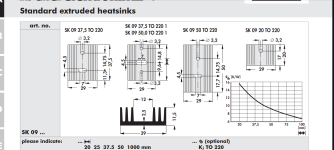
If you have a hard time relating a specific C/W rating to a physical heatsink then I'd suggest downloading the Fischer online catalogue as pdf and then browsing through it. Check some of the "common" profiles (SK104, SK129, SK85 just to give some examples) and see their ratings - that gives you some idea of e.g. what it takes to dissipate 5W.
Yes, this is kind of reverse guess for the C/W 🙂
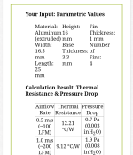
I have only the dimensions, both for the heatsinks at hand and for the ones I buy from local stores.
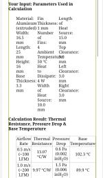
Both the calculators from the link above show results for a given airflow rate.
The minimal is 0.5 m/s.
I think a no fan heatsink, indoors, can't have such an airflow.
I have only the dimensions, both for the heatsinks at hand and for the ones I buy from local stores.
Both the calculators from the link above show results for a given airflow rate.
The minimal is 0.5 m/s.
I think a no fan heatsink, indoors, can't have such an airflow.


Perhaps more like 0.05 m/s, if the fins are vertical.
But go by the rule of thumb maximum 60C heat sink temperature.
But go by the rule of thumb maximum 60C heat sink temperature.
Or a power transistor.You can also clamp a chassis mount power resistor to your heatsink and connect it to a power supply to test the heatsink's cooling capacity.
You can regulate the total power dissipation with the base current, for example.
Then let the heat sink temperature stabilize. Temperature difference between ambient and heat sink (or transistor case) divided by power is the thermal resistance from heat sink to ambient air (or transistor case to ambient air).
I did transistor mounting tests using such a method.
Can't find a matching heatsink size/shape in catalogs (up till now).
I am amazed about the big one on the diagram - w 124, h 35, L 50 mm, base thickness 5 mm.
Tought it is a standard size and some manufacturer will have it in catalog with data.
Don't have it, plan to buy it. Intuitively feel it might be the right size.
Wondering if the extrusion length is 50 or better 70 mm, which would affect the enclosure design.
I tend to go for the slimmer, but wanted to verify somehow that it is ok for 19w dissipation (LM1875 power amp, mono), but it is extremely obscure to do so 🙁
Isn't there a formula for thermal conductivity by area, base plate thickness, material?
Last edited:
I would not be too picky about the physically exact thermal conductivity. The mounting method introduces much higher tolerances of heat conductivity.(LM1875 power amp, mono)
Also, what will be the use, supply voltage and resulting max and average power dissipation?
According to datasheet - ~20w/8 ohm, 19w power dissipation.
Use is a guitar amp in a small rehearsal room, so probably there won't be any need for continuous use at full power.
Mounting method... the datasheet states 2 C/W junction to case and 1.6 C/W for mica isolation pad - these have impact.
I got some formulas for calculating heatsing to ambient thermal resistance, but I am getting it wrong, depend on where I start from.
One result for heatsink area (just the fins, two sided) if I start with the power dissipation, and completely different, if I start with the area and come up to the max power dissipated...
===
Dt = 150 (junction max)-50 (ambient) = 100C
Pd (power dissipated) = 19 W
Rs (thermal resistance to dissipate) = Dt/ Pd = 100/19 = 5,263 C/W
Rcj (case to junction) = 2 C/W (lm1875)
Rcs = 1,6 C/W (thermal pad)
Rs (heatsink needed) = 5,263 - 2 - 1,6 = 1,663 C/W
Rb (heatsink base plate thickness) = 5 mm (0,005m)
thermal conductivity Aluminum = 205 W/m·K
S area = 205/(1,663 * 0,005) = 24654mm2 (246,5cm2)
===
S area = 600cm2 (0,06m)
Natural convection heat transfer = 10
Rsb = Rb / (205 * 0,06) = 0,05/ 12,3 = 0,00040650 C/W (unsignificant)
Rsink = 1/ 10 * 0,06 = 1,666
Rtot = 1,666 + 1,6 ( MICA thermal pad) + 2(R jc) = 5,27 C/W
Pd = Dt/ Rtot = 100/5,27 = 18,98 W
Last edited:
Do we put thermal paste on silicone pads at all ?
Here we have some Rc-heatsink for TO220
https://www.giangrandi.ch/electronics/thcalc/thcalc.shtml
mica, no paste - 1.5
mica, paste - 1.2
Silicone, no grease - 1.3
No data for silicone + paste
Here we have some Rc-heatsink for TO220
https://www.giangrandi.ch/electronics/thcalc/thcalc.shtml
mica, no paste - 1.5
mica, paste - 1.2
Silicone, no grease - 1.3
No data for silicone + paste
- Home
- Design & Build
- Parts
- Heatsink power dissipation
