Hi,
Just got a Heathkit IP-17 power supply.
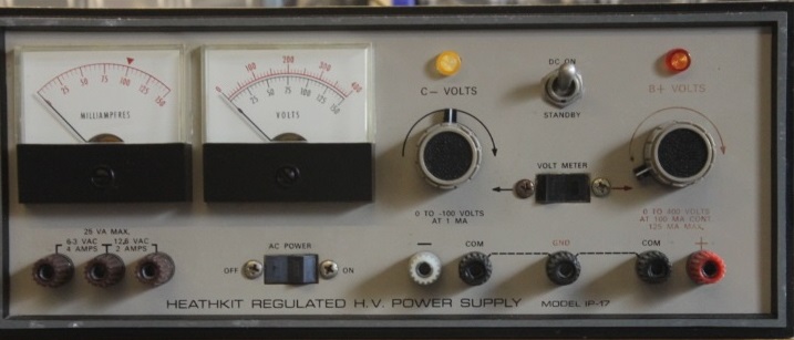
I will use it to put together small "flea power" tubes amps for fun, tear them down and put together another one with a different small type of tube, etc...
Now on the Heathkit power supply, on the front, there is the + and "common" high voltage outlets for the amp circuit.
Also there is a Ground one by itself, should I tie the ground to the "common" outlet of the heathkit?
Since the "breadboard" will be an old tube amp chassis, should I use the Heathkit ground for the chassis ground?
I dont mind soldering and unsolderings the parts on the chassis and using it as the negative/ground of the circuit. Would be more solidly tied together since I might listen to the test amp for a while on 2 sets of speaker in two different rooms.
Also, I might fool around with some preamp circuit.
So in fact, my "experiment" circuit would be: the B+ , and the chassis on the negative/ground from the Heathkit.
Should I install a fuse on that chassis?
Just like a normal tube amp.
But then, if the Heathkit only has a two prongs AC plug for the 120 Volt from the main (didn't received it yet). Should I install a 3 prong AC plug?
Kind of funny, but I love to fool around with tubes amps, but I'm pretty scare of these high voltages, hence all these questions...
What would be the best way to go about it.
Any suggestions, ideas, objections?
P.S. I already built/restored a few Tube amps: 300B SE. Dynaco ST-70, ST-35, TubelabSSE, restored a Fisher 500C and a pair of QuadII.
Search the forum for this, didn't find much.
Type of circuit I'm looking at:

Just got a Heathkit IP-17 power supply.
I will use it to put together small "flea power" tubes amps for fun, tear them down and put together another one with a different small type of tube, etc...
Now on the Heathkit power supply, on the front, there is the + and "common" high voltage outlets for the amp circuit.
Also there is a Ground one by itself, should I tie the ground to the "common" outlet of the heathkit?
Since the "breadboard" will be an old tube amp chassis, should I use the Heathkit ground for the chassis ground?
I dont mind soldering and unsolderings the parts on the chassis and using it as the negative/ground of the circuit. Would be more solidly tied together since I might listen to the test amp for a while on 2 sets of speaker in two different rooms.
Also, I might fool around with some preamp circuit.
So in fact, my "experiment" circuit would be: the B+ , and the chassis on the negative/ground from the Heathkit.
Should I install a fuse on that chassis?
Just like a normal tube amp.
But then, if the Heathkit only has a two prongs AC plug for the 120 Volt from the main (didn't received it yet). Should I install a 3 prong AC plug?
Kind of funny, but I love to fool around with tubes amps, but I'm pretty scare of these high voltages, hence all these questions...
What would be the best way to go about it.
Any suggestions, ideas, objections?
P.S. I already built/restored a few Tube amps: 300B SE. Dynaco ST-70, ST-35, TubelabSSE, restored a Fisher 500C and a pair of QuadII.
Search the forum for this, didn't find much.
Type of circuit I'm looking at:
Last edited:
The HV is floating, and either output can be grounded, depending on the polarity needed wrt ground.
Do connect one of the output terminals to ground for safety, though. Mine already has a 3 wire plug,
and adding that probably would be a good idea. To fuse your chassis, you'd have to use a DC rated fuse,
which is rare above 32VDC at small currents. Maybe a very thin wire segment would work.
http://www.pmillett.com/file_downloads/IP17.pdf
Last edited:
Hey, Thanx rayma,
So, I would tie the common and ground outlet on the Heathkit, that would connect the amp chassis to the earth ground throught the Heathkit and I will use the chassis as the circuit ground, and the positive would be the B+, just as a "standard" tube amp.
Like this, the Heathkit will act as the power supply for the amp.
I'll forget about the fuse on the chassis then. I suppose the Heathkit fuse would act as the whole circuit fuse then.
Thanx again rayma.
For safety, I would use lugs rather than banana plugs for connection to the Heathkit,
so it can't be accidentally be disconnected.
You might consider grounding the secondary of the Edcor output transformer.
so it can't be accidentally be disconnected.
You might consider grounding the secondary of the Edcor output transformer.
Last edited:
Yes, I intended to open up the Heathkit first thing upon getting it. It already had all the electrolytics cap replaced, so thats a good sign to start with. I will check a few things like the voltage and amperage coming out and sign of overheating on the differents components. Do you know if the diodes on the boards are reliable?
Thanx for the tips on the banana plugs, and the Edcor transformer. That i'll do at the speakers connectors.
Thanx for the tips on the banana plugs, and the Edcor transformer. That i'll do at the speakers connectors.
Mine has worked fine as-is, ever since finding it long ago. The caps do look cheap, so for heavy use
they should be replaced. The IP-17 is also handy for reforming electrolytics, using a series 10k 20W resistor.
They're finished cooking when the voltage across the resistor is less than 1V.
they should be replaced. The IP-17 is also handy for reforming electrolytics, using a series 10k 20W resistor.
They're finished cooking when the voltage across the resistor is less than 1V.
Last edited:
Yes, they're raw secondary winding voltages, and will vary with loading and the line voltage.
I think the power transformer is rated at 115VAC line voltage, so higher AC line will increase it 5%-10%.
I think the power transformer is rated at 115VAC line voltage, so higher AC line will increase it 5%-10%.
Last edited:
Make sure to measure the filament voltages -- in my IP17 they were off by several percent
If it's too high, can I use a resistor in serie to lower it a bit? Is it a good way to do it? Of course within 5%, I wouldn't worry too much about it...
With light loading, it's possible that the filament voltage could be up to 20% too high (7.5V).
You could use a Variac to adjust the AC line to 115VAC, to be per the original design.
Depending on circumstances, either a series resistor, or a parallel resistor, may work better.
The voltage will vary with loading. Check the wattage needed.
You could use a Variac to adjust the AC line to 115VAC, to be per the original design.
Depending on circumstances, either a series resistor, or a parallel resistor, may work better.
The voltage will vary with loading. Check the wattage needed.
Last edited:
If it's too high, can I use a resistor in serie to lower it a bit? Is it a good way to do it? Of course within 5%, I wouldn't worry too much about it...
I wouldn't worry about 5%, but my 6.3 is closer to 7.0 -- this is still within acceptable range, just something to know.
I have two of these, one was butchered to become a curve-tracer. Still works!
Hi guys,
A little update: got the heathkit IP-17, it's very clean and it's working
perfectly. A good purchase.
It's was re-cap, the tubes test very good on an Eico 666, Everything looks
very clean inside.
I mesured the voltage output and amperage output and the meters are right
on. I'm happy with my purchase.
I'll use it to supply all kind of fleapower amp while working at my
computer like I mentioned earlier on this thread.
Right now, it a SE amp using two 6CY7 pulling about 45 mA.
I listen to the amp for an hour or so, then give it a break.
Next Amp I wanna try is the same type of circuit but with two 6EM7 that
will pull around 80mA.
My question for the experienced tech out there: is it safe for that type
of power supply to use like that for hours at a time?
Thanx for any input.
Use a series resistor.
It will give you a free (automatic) soft start filament action.
But bring up the B+ as the filaments start to warm up, not before.
I have transformers that are rated for 115V and 117V.
To keep them cool, I draw far less current than they are rated for, because the primary is already starting to dissipate a little heat (not enough windings and or laminations).
A 50Hz transformer will have less heating on 60Hz power.
I have 3 bench supplies (low to high power) that were designed for a lower AC input than my house AC. In addition my line voltage does vary by a few volts.
I picked up a 10 amp variac for $50.
The supplies are connected to the variac. The first thing I do when I use them is adjust the variac so that I have 6.3 volts on the filament supplies.
Steve
I picked up a 10 amp variac for $50.
The supplies are connected to the variac. The first thing I do when I use them is adjust the variac so that I have 6.3 volts on the filament supplies.
Steve
Anybody know of a source for replacement panel meters for the IP-17?
Simpson "Tru-Vue" 922 meters -- available in 1mA and 150mA. Mounting studs are 1.88" and the panel face is 2.50"
They are available new from Avnet, but cost ~$95 each!
There's an Ebay seller with a 2.5mA meter which would fit the bill as well:
2-1/2” Inch Panel Meter: 0-20V & 0-1A Scales: 1mA Movement: 2/Lot: Nice Meter | eBay
I believe the with the Elenco meters you can remove the meter face and change the scale.
Last edited:
Thanx guys,
So, It's better to let it rest after a little while and not let it on for too long at the time so it wont get to hot. Now it's not bad, but it's only at 45mA with the little 6CY7 tubes amp.
Some amps I wanna try will pull up to 80/90 mA...
The main at my home is around 120 Volts pretty much all the time.
I get 7.1 Volts on the Heathkit Filaments supplie.
On the the amp Itself I used this trick to Drop the voltage on the tubes filaments (as seen on the upper right schematic):
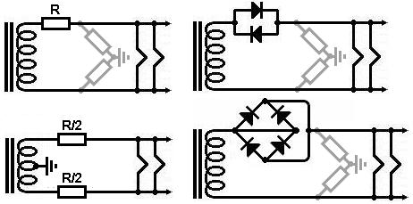
(I'm not using the resistors.)
I get 6.2 Volts on tube's filaments.
That's good for the little amp, but the Power supply is still a bit high for it's design, I suppose.
Do you think I could use 2 C-90 (120 ohms @ 2A) thermistors on the Heathkit primaries of the power transformer?
One thermistor on each lead.
I did that on a pair of QUADII, and it dropped the primary to around 116V after the thermistors.
Thanx for your time guys.
So, It's better to let it rest after a little while and not let it on for too long at the time so it wont get to hot. Now it's not bad, but it's only at 45mA with the little 6CY7 tubes amp.
Some amps I wanna try will pull up to 80/90 mA...
The main at my home is around 120 Volts pretty much all the time.
I get 7.1 Volts on the Heathkit Filaments supplie.
On the the amp Itself I used this trick to Drop the voltage on the tubes filaments (as seen on the upper right schematic):
(I'm not using the resistors.)
I get 6.2 Volts on tube's filaments.
That's good for the little amp, but the Power supply is still a bit high for it's design, I suppose.
Do you think I could use 2 C-90 (120 ohms @ 2A) thermistors on the Heathkit primaries of the power transformer?
One thermistor on each lead.
I did that on a pair of QUADII, and it dropped the primary to around 116V after the thermistors.
Thanx for your time guys.
I meant CL90 Thermistors. I had to use a reply to fix my mistake, I can't edit the post for some reasons...
- Home
- Amplifiers
- Tubes / Valves
- Heathkit IP-17 ground and common outlet