By now, most people know that twisting the AC heater wiring is recommended. But What happens if you ignore this?
I set up my PP 6P36S amp with AC heater wiring using a single conductor and the chassis for return.
It was wired from 12VCT with the CT grounded to chassis, each channels' tubes powered by one side of the coil. On testing there was a hum loud enough to annoy me. (about 10mV into 6R @ 60Hz). This was good by old standards really, but what about DC? So I rigged it up to use DC, full wave for 6V. There was 8V so I added a bridge to drop the voltage down to 6.3VDC for all 4 6P36S. I added 20,000uF of capacitance after the rectifier and bridge. Now the hum is louder, and at 120Hz.
Time for twisted pair on AC. Hum is %95 gone. The buzz of the power transformer is louder than any electrical hum. Just that easy.
For this test I also ran the VA/PI/Driver tube heaters from regulated DC.
The take away here is that high heater current output tubes can be better run from AC if you take the time to twist the wire I guess... Unless you're using an SMPS 😛
It may have been your method of rectifying and and filtering to get the DC heater supply. Did you use just a single heater winding to derive both the DC heater supply output stage and the regulated DC for preamp stages? Did you use a separate heater transformer?
With the AC heater, did you try a humdinger pot to check any improvement over a grounded CT ?
With the AC heater, did you try a humdinger pot to check any improvement over a grounded CT ?
Using the chassis for return might have been a big part of the problem. The chassis is supposed to act as shielding, but if you're using that as filament wiring I would expect that to cause a lot of problems with hum.
95% of the noise/hum problems I've had are grounding related. I've seen crappy grounding techniques in lots of DIY projects (including some of my own), and even in equipment from manufacturers who should really know better.
So what happens if you just run two parallel wires for the filaments but don't bother twisting them?
I have yet to see a hum issue caused by filament wiring unless it is done really, really poorly. Truth be told, in a pinch for testing I've run the filaments in a tube preamp off a transformer clamped to a board resting on the chassis and connected with a bunch of clip leads. Noise floor rose about 3dB to about -75dBu vs. -78dBu, and that was pretty much a worst-case-scenario with clip-leads running within five or ten millimeters of a signal wire. That preamp uses a pair of 12AU7s (or 12BH7s) running the filaments at 12V. It is a pretty standard design with a voltage gain stage and a cathode follower. It is not a differential input.
Last edited:
Using the chassis for return might have been a big part of the problem. The chassis is supposed to act as shielding, but if you're using that as filament wiring I would expect that to cause a lot of problems with hum.
Yes. Especially if the input and output connections are also grounded at the chassis. That will always give problems. Why?
A chassis is not zero ohms. Ground currents through the chassis set up very small voltage differences between areas of the chassis. That means that a small hum or noise voltage can exist between the area where the input is grounded and other points, which means that this hum is directly places in series with the input signal.
That is the basic principle between 'ground loops'.
Jan
Last edited:
While I agree using the chassis as connections is evil, it's not always the culprit.
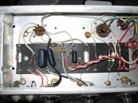
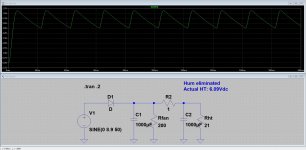
My 50 years old Fender Champ does just that, see photo; also note the very amateurish wiring typical of that era. With everything full up, the hum is annoying. I added a very basic half wave rectifier and a CRC filter as per the screen shot: now the hum is way below the hiss of the 1st stage.
My 50 years old Fender Champ does just that, see photo; also note the very amateurish wiring typical of that era. With everything full up, the hum is annoying. I added a very basic half wave rectifier and a CRC filter as per the screen shot: now the hum is way below the hiss of the 1st stage.
Attachments
I did not try parallel lines or a humdinger since it wouldn't work as the heaters are from one side of power to ground, not across the entire secondary (12V, Hammond 167V12). The first stage heater ran from an SMPS, the second stage heater was regulated DC from the main power transformer, the power tube heaters are powered from their own transformer. Rectification was a simple full wave into 20,000uF. Chances are if I had made the DC "clean" no hum would have resulted, but I would have wasted 20W in regulation.
I use the chassis as return most of the time, but I'm usually using SMPS so it's hum-less. Indeed the first two stages are using the chassis for return of their DC power. I feel it would have been much worse if I had used a steel chassis rather than aluminum.
I use the chassis as return most of the time, but I'm usually using SMPS so it's hum-less. Indeed the first two stages are using the chassis for return of their DC power. I feel it would have been much worse if I had used a steel chassis rather than aluminum.
Last edited:
Running current through a conductor creates a magnetic field, of course. Your trouble is with magnetism. Cancellation by twisting the conductors is important but still you should consider the resulting magnetic field as a source of noise to your circuit. The recommendation is to capacitively couple the twisted conductors to ground and place them in the far fold (edge) of the chassis.
Edit: Except for experiments I build with worst case in mind. Even runs of DC power cables go twisted to achieve a little bit of attenuation from the PS stray field.
Edit: Except for experiments I build with worst case in mind. Even runs of DC power cables go twisted to achieve a little bit of attenuation from the PS stray field.
Last edited:
- Home
- Amplifiers
- Tubes / Valves
- Heater wiring experiments and conclusions...