I was looking at some old Fender guitar amplifier layouts and noticed that they use a single wire to one side of a tube's filament and ground the other. For example, the 6.3V wire goes to pin 2 of a 6V6 and pin 7 goes to ground.
I am building an amp with 6V6 and 6SN7 tubes. I thought all I needed to do is twist the two filament wires together and connect one to pin 2 and the other to pin 7 for the 6V6, then run the wires to pins 7 and 8 for the 6SN7. Am I right?
Do I need to ground the filaments?
Why would you do one approach over the other?
DON'T run heater current through the chassis! That's just ASKING for hum! The heater circuit DOES need be tied to ground, though - to avoid common-mode noise... but only at ONE point. Depending on how much gain you have, the following are in increasing order of effectiveness and effort as well:
1) ground one side of the heater winding
2) ground the center-tap of the heater winding or make an artificial center-tap with two 100 Ohm resistors
3) bias the heater center-tap ~ 20V positive, with a capacitor to provide an "AC" ground
4) rectify and filter for DC heaters, one side of DC grounded
5) Regulated DC, one side grounded
For a power amp, (1) should be enough.
Run the wires as you indicated, and if there is a center tap for the filament winding, run it to the top of the 6v6 cathode. Otherwise just use two resistors to place the DC cathode voltage in the "center" of the AC winding. This will cause the hum to be reduced by biasing off the heater-cathode "diode".
This will also help protect the heater-cathode insulation if you are using cathode followers or other topologies that place high voltage on the cathodes. If so, check the spec sheet to make sure you're still operating within the heater-cathode voltage spec.
This will also help protect the heater-cathode insulation if you are using cathode followers or other topologies that place high voltage on the cathodes. If so, check the spec sheet to make sure you're still operating within the heater-cathode voltage spec.
more hum reduction
A couple of additional things...keep the twisted heater wires away from the signal wires where possible. If they must cross, try to do it at right angles, ie don't run the heater wires parallel/next to signal wires if you can help it.
Run the heater wires around the edges and corners of the chassis, coming out to connect to the socket and then back to the edges/corners. Using solid core wire allows the wire to stay where you put it.
Also, when running the twisted wires to and from each tube socket do not "jump over" the socket to continue the wiring. Instead, come up to the socket and leave the socket from the side without enclosing the socket between the wire runs, this also cuts down on hum.
I do not have a center tap for the filaments, just a green and a blue wire which I have represented in the attached diagram.
Tom Bavis suggests grounding one side of the heater wiring. I'm new at doing this solo so I want to be absolutely clear...
I could simply connect pin 2 of the left-hand 6V6 to ground? That's it, or am I missing something?
Similarly, I could just as easily connected pin 7 to ground, or even pin 8 of the 6SN7. Doesn't really matter just as long as only one side is connected to ground.
Now, for m6tt's suggestion (which sounds similar to Tom Bavis option 2). My circuit is extremely simple - basic grounded-cathode amplifier. I don't think I have to worry about the heater-cathode voltage spec.
Anyway, the suggestion is to create an artificial center tap with two resistors (100R) and run it to the "top of the 6V6 cathode".
Does this mean that I would connect one resistor from pin 2 to pin 8 and one resistor from pin 7 to pin 8? I am building a grounded cathode amplifier and will have the cathode resistor and bypass cap going from pin 8 to ground. Seems like this would cause the heater voltage to go through the Rk to get to ground. That doesn't sound right (but I don't know, maybe its ok to do).
Or, would I connect one resitor from pin2 to ground and one resistor from pin 8 to ground?
Again, thanks for the help... I'm getting close to understanding.
Attachments
M6tt's suggestion is my (3) - bias the center tap positive. NO direct ground connection on the heater! The heater winding is biased positive by the 6V6 cathode voltage, and the cathode cap provides the AC ground to bypass common-mode noise.
Heater current doesn't flow through the cathode resistor - it flows in one transformer wire and out the other.
Heater current doesn't flow through the cathode resistor - it flows in one transformer wire and out the other.
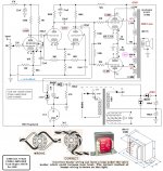
See attached for virtual center tap.
Upper sketch is grounded virtual center tap and lower sketch is elevated center tap.
An optional cap in parallel with the lower B+ divider R is not shown, but can/should be added per Tom B #3 above.
The values or R1 and R2 depend on your B+ voltage an how much elevation you need. No current flows, it's a voltage reference only. Let's say your B+ is 300V, then R1 could be 280K and R2 could be 20K, that would form a simple voltage divider that would reference the virtual center tap to 20V
Tom: What size cap is typically used for AC ground?
Attachments
Sorry to sound thick but... is my diagram correct or do I need to do anything else?
What would creating an artificial center tap do for me.
What would creating an artificial center tap do for me.
Last edited:
Sorry to sound thick but... is my diagram correct or do I need to do anything else?
What would creating an artificial center tap do for me.
It references the heater voltage to ground (or an elevated voltage), reducing hum. Slightly elevating the reference voltage reverse biases the diode effect of the heater-cathode in the tube (or something like that-I'm also a newbie) reducing noise even further.
Reason for a center tap is that instead of 6.3VAC with respect to ground, you have two 3.15V levels of opposite polarity - much of the hum coupling cancels. A voltage divider can be use to elevate the heater winding, but using the 6V6 cathode voltage saves those three parts (third part is the bypass cap). The 6SN7 is the most sensitive spot, since any noise that gets in there gets fully amplified...
Source of the common mode noise is the power transformer - there is capacitance from primary to heater winding, maybe as much as 50-100 pF. And there's capacitance from heater to cathode, and a parasitic diode that can conduct on AC peaks. High frequency noise can couple through this, unless the heater winding has a ground connection or is bypassed to ground.
Source of the common mode noise is the power transformer - there is capacitance from primary to heater winding, maybe as much as 50-100 pF. And there's capacitance from heater to cathode, and a parasitic diode that can conduct on AC peaks. High frequency noise can couple through this, unless the heater winding has a ground connection or is bypassed to ground.
Sorry to sound thick but... is my diagram correct or do I need to do anything else?
What would creating an artificial center tap do for me.
I believe your post 5 drawing is Ok
Take a look to this one:
Attachments
So connect the center tap to the cathode of the 6V6?.....since it's cathode biased and has a bypass cap we get double-duty out of those parts-a little elevated voltage and an AC ground? Learn something new every day.
So connect the center tap to the cathode of the 6V6?.....since it's cathode biased and has a bypass cap we get double-duty out of those parts-a little elevated voltage and an AC ground? Learn something new every day.
There is a parasitic diode from the cathode to the heater. If this diode is forward biased by having the heater potential significantly below the cathode potential, you get an excellent coupling path for hum between the heater and the cathode. The trick is to connect the heater to the cathode. This shorts out the parasitic diode so it never conducts. I use a pair of 100 kOhm resistors to do this. If the heater winding has a center tap, I suppose you could use only one resistor and tie the center tap to the cathode through the resistor. You don't actually want any current flowing in this resistor as this will shunt the AC signal to ground. You just want to establish a DC potential to shut off that pesky parasitic diode.
I haven't measured if it actually makes a difference with the resistors in place or not. But resistors are cheap, so why not use a pair...?
~Tom
In your wiring diagram, I would wire the heaters from the transformer, to the two 6V6s then to the 6SN7. The 6SN7 is the most sensitive component to hum, so the least amount of current passing through the heater wiring when it gets to the input stage the better.
Do I simply attach 100K ohm resistors from pins 2 and 7 to pin 8 on the last tube socket?
Is the attached diagram correct (not considering putting the 6SN7 last)?
Do I need to do this on each socket or just one as shown in the diagram?
What power rating should the resistors be? I'm assuming 1/4 Watt is fine (~0.0004 = 6.3*6.3/100000).
Is the attached diagram correct (not considering putting the 6SN7 last)?
Do I need to do this on each socket or just one as shown in the diagram?
What power rating should the resistors be? I'm assuming 1/4 Watt is fine (~0.0004 = 6.3*6.3/100000).
Attachments
Last edited:
Just one.Do I need to do this on each socket or just one as shown in the diagram
Blue, what drawing program are you using for your little diagram. Seems useful. thanks.
I use Visio. I created my own stencil for schematics and layout. I add new items to the stencil as I need them so not all components are represented, but it works from me. If people are interested, I will find a place to post it for download.
The layout items are all drawn by hand to scale. For example, I traced an engineering drawing of a Kiwame resistor for the resistors, then scaled the height and width based upon the manufacturer's specifications. I did the same with the socket.
This lets me rotate and place the virtual components first to find a good layout. Of course, I have yet to try to convert a virtual layout to a real one.
- Status
- Not open for further replies.
- Home
- Amplifiers
- Tubes / Valves
- Heater wiring approaches