This is also from a Philips source.
Yet, I don't see a catastophe when running at 6.42 instead of 6.3, which is 2% high ...
Note the top curve is mislabelled, should be 7.5, NOT 5.7.
Note2: the lower values may extend tube life but may lower performance.
This is from an article on tube life I wrote for AudioXpress a few years ago:
https://audioxpress.com/article/the-internal-life-of-vacuum-tubes
Jan
Attachments
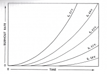
Neither axis of the graph has a scale, so we can't tell whether it's a catastrophe or not.I don't see a catastophe when running at 6.42 instead of 6.3, which is 2% high ..
But it is in general agreement that above-nominal voltage reduces lifetime - which is the important point.

Jan, Interesting article all round.article on tube life I wrote for AudioXpress
As the cathode heats up, the temperature will not be uniform and the hotter areas will allow more current than the cooler areas. The current that flows will tend to concentrate in small hot areas, and that will increase the current density to higher values than will be the case at normal operation. That higher current density can locally damage the cathode
Did the part about the uneven anode-current distribution across the cathode derive from the van Mosselvelde interview?
I would have to look that up.
BTW Tomer lists heater regulation as one of the most effective means to prolong tube life, especially with continuously rising line voltages.
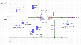
I've been building some stuff with heater supply by switching regulators. Very effective and very efficient, using the TPS5402 and TPS54331 parts.
Just rectify the 6.3V and feed it into the switcher. No audio degradation I could detect.
You can fit the whole regulator inside the tube socket area on a PCB.
Jan
BTW Tomer lists heater regulation as one of the most effective means to prolong tube life, especially with continuously rising line voltages.
I've been building some stuff with heater supply by switching regulators. Very effective and very efficient, using the TPS5402 and TPS54331 parts.
Just rectify the 6.3V and feed it into the switcher. No audio degradation I could detect.
You can fit the whole regulator inside the tube socket area on a PCB.
Jan
Attachments
Yes, he said that the temp difference between the ends of the cathode tube and the center could be up to 40C.Did the part about the uneven anode-current distribution across the cathode derive from the van Mosselvelde interview?
Jan
🙂 I take the switchers run exactly the nominal voltage don't they? They also regulate which is a big bonus.
As mentioned voltage regulation was a rare thing in the fifties (hence the tolerances) but today it isn't. Steady DC regardless of mains voltage variations, slow startup, all possible with a handful of parts. If you like to fight/solve EMI issues in a fully analog device and if you like repairs once in a while SMPS are good too. At least they keep you busy.
You already answered your question yourself. Good solution, a 4.7 ... 5.6 Ohm of the right power rating in series with the 10 Ohm is OK.Non regulated DC.
It's a function of the B+.View attachment 1070510
The voltage can be lowered by changing R15. Currently it's 10 Ohm.
A change to 16 Ohm would put me pretty much bang on 12.6V.
20 Ohm would put me slightly under at 12.45V.
As mentioned voltage regulation was a rare thing in the fifties (hence the tolerances) but today it isn't. Steady DC regardless of mains voltage variations, slow startup, all possible with a handful of parts. If you like to fight/solve EMI issues in a fully analog device and if you like repairs once in a while SMPS are good too. At least they keep you busy.
Last edited:
Tomer was a professional worry-wart.BTW Tomer lists heater regulation as one of the most effective means to prolong tube life
12AU7 do not fail from heater burn-out, not in most people's lifetime. They also, in audio use, do not fail from under-heating, because 12AU7 emission is about 10X what we need.
Broskie's plan is strange because this is one of those stacked-triode affairs, with upper cathode halfway up B+. And because Broskie likes strange ideas. If we don't like his teachings we don't have to take it.
I've enjoyed the sonic results of Broskie's aikido topology.
This particular one was purchased for a canceled experiment in combining a tube line stage with a solid state power stage as an integrated amp.
The fact that all one needs for this is a single transformer secondary for the whole board makes it quite amenable for such use.
Due to the high psrr of the aikido design, the rather rudimentary power supply works well. It's not as good as another aikido linestage I have with regulated b+ and heaters but it's surprisingly close given its simplicity.
So, with the specification of mains supplies being +10 -5% no manufacturer regulates the heater supply voltages unless because it wants to for added sales blurb.
I have never seen a valve sufer with 7volts on the heaters or even 5.5volts. The emmisions will reduce below 5volts but do not change above 6.3v.
I had a Chinese amplifier in for repair to find the phase splitter was designed around a 12AU7 and a 6P2 had been fitted by mistake some years before.
A 6P2 has 6.3v heaters between pins 4 & 5 with pin 9 screen where a 12AU7 has 12.6v heaters between 4 & 5 pin 9 centre tap.
Three years at twice the heater voltage and no noticeable issues except for the extra bright heaters.
That was what it came in for, no issues apart from the brightly glowing valve.
A lot of what Tomer put in his book was 'folk wisdom' rather than proven info. That graph is kinda kookie and appears to have been sketched from his imagination. Heater 'burnout' is one of the least relevant things for overall lifetime, assuming you're within the usual 10% voltage spec.
One of the points of that Philips QC guy I quoted was that a too high heater current causes a too high cathode temperature.
This accelerates the evaporation of all those oxides and whatnot on the cathode, bariumcarbonate etc.
If the cathode gets too hot, the tube lifespan gets drastically shorter because of cathode exhaustion.
Jan
This accelerates the evaporation of all those oxides and whatnot on the cathode, bariumcarbonate etc.
If the cathode gets too hot, the tube lifespan gets drastically shorter because of cathode exhaustion.
Jan
G'day guys,
So after measuring the mains voltage and heater voltage for a few days at different times.
My findings are that at the nominal 230v mains I get bang on 12.6v at the heaters.
At 236v at the mains I get 12.9v on the heaters.
At 224v at the mains (a particularly cold and stormy winter night at 8pm) I get 12.25v at the heaters.
Given all this I am thinking that my heater voltage is pretty much exactly what might be expected from the variation in the mains.
Thus I think I will leave well enough alone and not change the dropping resistor.
Thanks for all the advice guys.
What's more important is overall tube temp envelope temp and installing them in a way they have the ability to cool, both from the heaters and the plate current. I see so many designs where the tubes are all jammed together or beam power tubes are installed with no consideration to orientation, all of which will kill tubes way faster than a couple of percentage points of heater voltage will. I've had tubes running a few % overvoltage specs for years, that otherwise have decent cooling designs, so not sure how "drastically" the life is actually being shortened.One of the points of that Philips QC guy I quoted was that a too high heater current causes a too high cathode temperature.
This accelerates the evaporation of all those oxides and whatnot on the cathode, bariumcarbonate etc.
If the cathode gets too hot, the tube lifespan gets drastically shorter because of cathode exhaustion.
Jan
My personal feeling is adding super hot running dropping resistors under the amp, to try to drop the high current heaters a couple of percentage points, is going to build up excessive heat inside the amp destroying capacitors and other passives, creating more overall harm than what you are trying to resolve.
That reason is the cell voltage of a lead acid cell is 2.1V... Six in series makes 12.6V... 12.6V + 10% = 13.8V which is also the old standard charge voltage for a 12.6V lead acid battery. 12.6V - 10% = ~ 11.4V which is typical of a lead acid battery is a state of low charge.They don't mention 12.6V (yes with a capital V) without a reason.
FWIW I once ran 6.3V tubes at 12.6V for a week before I noticed the switch was in the wrong position... Those tubes still work 10 years later (6SL7). Don't lose any sleep over it 😛
Precision is fine for precision circuitry. A tube heater is not a precision device.
Last edited:
Absolutely. ±10% is common, ±5% I've seen on some tubes, too.
Just saying if +100% didn't destroy the thing in a week, don't worry about a couple hundred mV extra 😀
Just saying if +100% didn't destroy the thing in a week, don't worry about a couple hundred mV extra 😀
Those old dead guys are not as dumb as they look.my heater voltage is pretty much exactly what might be expected
Certainly smarter than me.Those old dead guys are not as dumb as they look.
I'm just a monkey with enough brain to be dangerous.
- Home
- Amplifiers
- Tubes / Valves
- Heater Voltage too much?