Hey Guys,
Some general questions.....
With respect to Heater to Cathode Potential, what are the general rules of thumb.
Specifically, when does one need to raise the reference voltage of the heater above ground?
DHT vs IDHT?
AC vs DC?
What are the physical and sonic differences?
Thanks,
Bryan
Some general questions.....
With respect to Heater to Cathode Potential, what are the general rules of thumb.
Specifically, when does one need to raise the reference voltage of the heater above ground?
DHT vs IDHT?
AC vs DC?
What are the physical and sonic differences?
Thanks,
Bryan
A DHT heater is the cathode, so they are at the same potential. In an autobias ( cathode bias) DHT amp, the cathode resistor lifts the heater /cathode above ground. DC is recommended for a heater supply for hum reduction. Do not ground the heater supply! 😀
For IDHT like 6SL7, 6SN7, there are heater to cathode maximums that must be observed when using circuits like SRPP, cathode follower. The numbers can be found in the data sheets for each. This can be achieved by using a reference voltage from the B+ and attaching this to the floating heater winding.
For IDHT like 6SL7, 6SN7, there are heater to cathode maximums that must be observed when using circuits like SRPP, cathode follower. The numbers can be found in the data sheets for each. This can be achieved by using a reference voltage from the B+ and attaching this to the floating heater winding.
> Do not ground the heater supply!
I did not understand this. With a floating cathode, how could you measure plate potential ? I will be appreciated if you explain it.
MB
I did not understand this. With a floating cathode, how could you measure plate potential ? I will be appreciated if you explain it.
MB
As ShiFty implies, if you were to ground the heater of a directly heated valve using cathode bias, you would be short-circuiting the cathode bias resistor, which would cause unrestricted current flow, upset the operating point, and possibly destroy the valve. Not a good idea.
Hi,
With totem pole type circuits it's easier to use twin triodes where top and bottom share the same enveloppe.
It makes it easier to bias the heater close to cathode potential that way.
Ideally heater and cathode should be at the same potential to avoid secondary emission from either one of them.
Cheers,😉
For IDHT like 6SL7, 6SN7, there are heater to cathode maximums that must be observed when using circuits like SRPP, cathode follower. The numbers can be found in the data sheets for each. This can be achieved by using a reference voltage from the B+ and attaching this to the floating heater winding.
With totem pole type circuits it's easier to use twin triodes where top and bottom share the same enveloppe.
It makes it easier to bias the heater close to cathode potential that way.
Ideally heater and cathode should be at the same potential to avoid secondary emission from either one of them.
Cheers,😉
Frank,
This being said, would I get any benefit from raising the heater potential in my 12B4A linestage. Currently it is sitting at a humble "0" volts.
Thanks,
Bryan
This being said, would I get any benefit from raising the heater potential in my 12B4A linestage. Currently it is sitting at a humble "0" volts.
Thanks,
Bryan
Hi,
Thinking right but writing wrong....
I mean the top triodes being the same tube and the bottom a different one.
I realise the quotation can be confusing.
Bryan,
How's that? Is the cathode grounded?
If it is it can't emit anyway so you're safe.
Cheers,😉
With totem pole type circuits it's easier to use twin triodes where top and bottom share the same enveloppe.
Thinking right but writing wrong....
I mean the top triodes being the same tube and the bottom a different one.
I realise the quotation can be confusing.
Bryan,
Currently it is sitting at a humble "0" volts.
How's that? Is the cathode grounded?
If it is it can't emit anyway so you're safe.
Cheers,😉
Hi, Frank -
Do you know how bad secondary emission can get in what would be considered a 'good' miniature tube with a heater/cathode potential up to 100VDC over its lifespan?
This may impact how I configure the driver stage in my hybrid amp. If as a voltage/current gain stage, its cathode will be sitting nearly two hundred volts below ground, so I'll probably split the cathode potential halfway between that and ground, but I'm afraid that secondary emission might then deteriorate my dc offset stability.
Thanks in advance for any input.
-thoriated
Frank,
Let me clarify.
The cathode is at approximately +9volts. The heater is referenced to ground. The anode is at about 100V.
Sorry about the confusion....
Let me clarify.
The cathode is at approximately +9volts. The heater is referenced to ground. The anode is at about 100V.
Sorry about the confusion....
Hi,
You'll probably never notice secondary emission effects in an audible way, I think.
However, if we were to cross the limits stated by the manufacturer, or you have a somewhat dodgy tube where the heater is at some point too close to the cathode sleeve, we risk a sticky heater and that can give us a very nasty bang.
Inbetween, before it actually sticks, you may experience HF oscillations capable of killing your amps, tweeters and drive all pets from the room.
Whether your hearing is good or not so good, this one won't pass unnoticed, believe me.
Below ground potential meaning you run it from a bi-polar supply?
The same would apply as if it was above ground, i.e. positive, so the same precautions should be taken.
As an example and regardless of max. heater to cathode voltage diffs. if the cathode has a potential diff. of 100V with respect to the heater I'd bias the heater upwards so the final diff. equal 0 volts.
This is the theoretically ideal situation according to the Philips engineers.
Cheers,😉
Do you know how bad secondary emission can get in what would be considered a 'good' miniature tube with a heater/cathode potential up to 100VDC over its lifespan?
You'll probably never notice secondary emission effects in an audible way, I think.
However, if we were to cross the limits stated by the manufacturer, or you have a somewhat dodgy tube where the heater is at some point too close to the cathode sleeve, we risk a sticky heater and that can give us a very nasty bang.
Inbetween, before it actually sticks, you may experience HF oscillations capable of killing your amps, tweeters and drive all pets from the room.
Whether your hearing is good or not so good, this one won't pass unnoticed, believe me.
If as a voltage/current gain stage, its cathode will be sitting nearly two hundred volts below ground, so I'll probably split the cathode potential halfway between that and ground, but I'm afraid that secondary emission might then deteriorate my dc offset stability.
Below ground potential meaning you run it from a bi-polar supply?
The same would apply as if it was above ground, i.e. positive, so the same precautions should be taken.
As an example and regardless of max. heater to cathode voltage diffs. if the cathode has a potential diff. of 100V with respect to the heater I'd bias the heater upwards so the final diff. equal 0 volts.
This is the theoretically ideal situation according to the Philips engineers.
Cheers,😉
Hi,
C = +9V
F = +12.6V (as an example)
A = Anode, don't play.
All voltages measured with respect to true 0 volt; ground.
Heater is grounded at one end, the negative leg.
So the heater is 3.6V high with respect to C. No problem whatsoever.
Don't go paranoid over this secondary emission, a few volts aren't going to start an electron war inside the tube.
I was just crossing the Ts and dotting the I's, this is much more important with CRTs and labtests than I'd imagine it to be for audio purposes anyway.
Cheers,😉
The cathode is at approximately +9volts. The heater is referenced to ground. The anode is at about 100V.
C = +9V
F = +12.6V (as an example)
A = Anode, don't play.
All voltages measured with respect to true 0 volt; ground.
Heater is grounded at one end, the negative leg.
So the heater is 3.6V high with respect to C. No problem whatsoever.
Don't go paranoid over this secondary emission, a few volts aren't going to start an electron war inside the tube.
I was just crossing the Ts and dotting the I's, this is much more important with CRTs and labtests than I'd imagine it to be for audio purposes anyway.
Cheers,😉
Below ground potential meaning you run it from a bi-polar supply?
That's correct, at +/- 175VDC, and the input stage of the 6K11 will have its cathodes at ground potential. I have some concern that secondary emission may degrade long term dc offset stability in some cases with the filament at, say, -85VDC if this topology is used.
Hi,
You're quite likely pretty safe.
Emission starts to occur at 30V potential difference, do you happen to have a diagram of the cct for us to look at?
Cheers,😉
I have some concern that secondary emission may degrade long term dc offset stability in some cases with the filament at, say, -85VDC if this topology is used.
You're quite likely pretty safe.
Emission starts to occur at 30V potential difference, do you happen to have a diagram of the cct for us to look at?
Cheers,😉
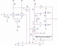
Hi, Frank -
This is probably more or less how it would look (I am using the driver as an inverted gain stage instead of a follower here) except that I'll be running the supply voltages somewhat lower, say +/- 170VDC instead of 200VDC. However, that still comes rather close to the maximum cathode heater ratings for the 6K11 with the heater potential centered between ground and the negative -170 V supply. Do you think secondary emission might adversely affect bias points over time?
TIA. OTLs forever!
Attachments
Hi,
Since I can only guess the voltages on the cathodes, I suggest you build it as you want, measure all cathode to heater voltages on all sections of the 6K11 to start with.
The problem you'll be facing is that the potentials are likely to vary rather wildly from one section to the next so we'll need to find some compromise.
Sorry, I can't be of more help to you right now.
Maybe someone with more insight into semi-conductor than i do can help you out on this one.
Cheers,😉
Thoriated: Looking at your diagram, you seemed to be in semiconductor mode when assigning values to your global feedback loop. You can cheerfully scale your resistors by a factor of at least ten, allowing you to use a much smaller capacitor than that 10uF you currently have.
You definitely need separate heater supplies for the input pair and the voltage amplifier. Expect DC problems if you don't.
You definitely need separate heater supplies for the input pair and the voltage amplifier. Expect DC problems if you don't.
Hi,
Thing is, it's a single 3 section compactron...
Cheers,😉
You definitely need separate heater supplies for the input pair and the voltage amplifier.
Thing is, it's a single 3 section compactron...
Cheers,😉
Hi,
My thoughts exactly...Unless, perhaps Thoriated wants to change to a 12AX7A + a not sure here, EC90??
1/2 a ECC82 like the EC92 is half a ECC81.
Checking Duncan Amps.......yes, a 6C4.
Cheers,😉
Oh dear. That puts a rather large spanner in the works.
My thoughts exactly...Unless, perhaps Thoriated wants to change to a 12AX7A + a not sure here, EC90??
1/2 a ECC82 like the EC92 is half a ECC81.
Checking Duncan Amps.......yes, a 6C4.
Cheers,😉
- Status
- Not open for further replies.
- Home
- Amplifiers
- Tubes / Valves
- Heater To Cathode Potential