Is it possible to run the heaters of a indirectly heated rectifier tube and the other tubes in the circuit off the same winding without tying the cathode to the heater on the rectifier as long as you elevate the "center tap" reference to ground? Say, I have a B+ of around 450V, but no additional filament winding.
Will this work?
Will this work?
Attachments
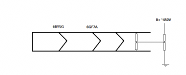
Don't do it! The filament winding associated with a directly heated rectifier is at B+ potential. 
SS rectify that B+ rail. Directly heated rectifiers turn on almost as fast as SS diodes do. Install a CL-130 inrush current limiter between the SS diodes and the PSU filter and you'll do fine.
SS rectify that B+ rail. Directly heated rectifiers turn on almost as fast as SS diodes do. Install a CL-130 inrush current limiter between the SS diodes and the PSU filter and you'll do fine.
The 6BY5 is a indirectly heated rectifier isn't it?
I just figured applying the same heater elevation method as used for small signal tubes might work.
I just figured applying the same heater elevation method as used for small signal tubes might work.
Thanks Eli!
So, theoretically, to close the heater to cathode potential I could reference the heater center tap at 1/4 B+?
So, theoretically, to close the heater to cathode potential I could reference the heater center tap at 1/4 B+?
Hi,
So, you think it will work? What value cap, and what wattage resistors? On line stages, I usually use 1W resistors.
Thanks!
So, you think it will work? What value cap, and what wattage resistors? On line stages, I usually use 1W resistors.
Thanks!
Arbitrary 'large' value, say 22µF or 47µF. A smaller would suffice, but no matter.
Wattage of resistors can be calculated using ohm's law. Let's say the resistors are 220k and 33k, and B+ is 300V.
Total current of thru resistor string is I = 300 / (220k + 33k)
Then calculate voltage drop over 220k resistor U = I x 220k
Power dissipation is then U x I, so around 0.3 W. 1W resistors are fine.
As to the concept in general; on paper, it should work. Whether or not it's a good idea I cannot say. When I used tube rectifiers, I always had a separate winding for their heater.
EZ80 seems to have 500V cathode insulation. There might be some other recs that have more safety headroom.
EZ80 seems to have 500V cathode insulation. There might be some other recs that have more safety headroom.
Hi deicide67,
Don't do this. As Eli recommended, use solid state diodes. If you want to copy tube performance, add resistance in series with the rectifiers (normally you should anyway, even with tube rectifiers), and a zener to mimic the voltage drop and there you go.
You have an opportunity to save some heater power which will drop the core temperature slightly. Why wouldn't you take this opening that has nothing but benefits??
A good rule to follow is to never bring tubes (or semiconductors) close to the limits of operation. Most tubes have a H-K breakdown voltage of 100 VDC or so. This rectifier has 500V, okay. But your circuit will probably perform better using the diodes, and you can avoid a problem in reliability down the road.
-Chris
Hey Chris,
I'm not opposed to SS rectification. I just figured that I would use the tube rectifier to drop the B+ a little. Plus, I had a hole in my chassis for one 🙂
Anyway, I am fine with adding something like a 50 ohm in series with the secondaries before the rectifiers and adding a CL to the mains for slow ramp up.
Thanks!
Hi deicide67,
Those resistors will reduce the peak currents a lot. This will then cut down on any diode ringing you might have had to deal with. The voltage will drop very quickly using these resistors as well. The positives coming from using these resistors just keep on coming!
If you look at tube rectifier data sheets you will often find a minimum resistance that is recommended in series with each plate. Again the goal is to reduce the hot switching currents. Adding inrush current limiting can't hurt either.
Now, that hole. You could put a tube in there with an open heater and light it up with an LED. Either that, or you could use it for another R-C-R-C section. Making the first one 8 ~ 22 uF would drop the voltage a little more, and give you much better filtering of the B+. I'm not a fan of > 47 uF capacitors for the input filter cap of a tube amp.
-Chris
I'd just use the extra hole for air flow, ventilation. But then again I'm not very big on nice looking builds...
If you want a nice soft start, get a single TV damper diode. They are available with sufficiently rugged ratings. Then just put the diode not as rectifier, but instead between PSU caps.
If you want a nice soft start, get a single TV damper diode. They are available with sufficiently rugged ratings. Then just put the diode not as rectifier, but instead between PSU caps.
I like that idea a bit since it covers the hole. I may just order a 6AX4. Plus, it uses less heater and I will be well within the H/K breakdown range.
Thanks!
Thanks!
What's the safety concern if it is properly fused and the heater cathode tolerance is 900V?
I'm serious. Just asking. I do not know.
I'm serious. Just asking. I do not know.
There is no safety concern. Just use the recto like any other valve and elevate the heaters accordingly. Job done.
deicide67, has your amplifier got fusing on the power transformer high voltage secondary winding?
Many older amps didn't include that fuse protection - it is worth the effort to add. That fuse could be good insurance against a lot of possible failure mechanisms, including heater-cathode failure in the rectifier diode, depending on how the heater is grounded.
Many older amps didn't include that fuse protection - it is worth the effort to add. That fuse could be good insurance against a lot of possible failure mechanisms, including heater-cathode failure in the rectifier diode, depending on how the heater is grounded.
Is it possible to run the heaters of a indirectly heated rectifier tube and the other tubes in the circuit off the same winding without tying the cathode to the heater on the rectifier as long as you elevate the "center tap" reference to ground? Say, I have a B+ of around 450V, but no additional filament winding.
Will this work?
Maybe. There are some power diodes that are indirectly heated, but internally the cathode is connected to the heater. These types are no different from DH diodes like the 5U4GB, and that heater winding mustt float.
The only power diodes with separated, insulated, IDH cathodes are the TV damper diodes. These can be operated off the same PTX windings, and that was routine in television practice. Even so, it would still be a good idea to use a separate heater PTX to avoid capacitive coupling of AC noise into the heater supply of the signal tubes. It wasn't such a big deal in TV sets since the horizontal scan rate was very much higher in frequency than AC mains ripple.
- Status
- Not open for further replies.
- Home
- Amplifiers
- Tubes / Valves
- Heater cathode elevation