Hi All,
First of all I just want to say Hi. This is an excellent community and I've found everything I read here really helpful. You guys seem really helpful and friendly 🙂
I'm posting today to get your comments and criticisms on a power supply and headphone amplifier that I've designed. I've based the design from quite a few found on this forum and the internet.
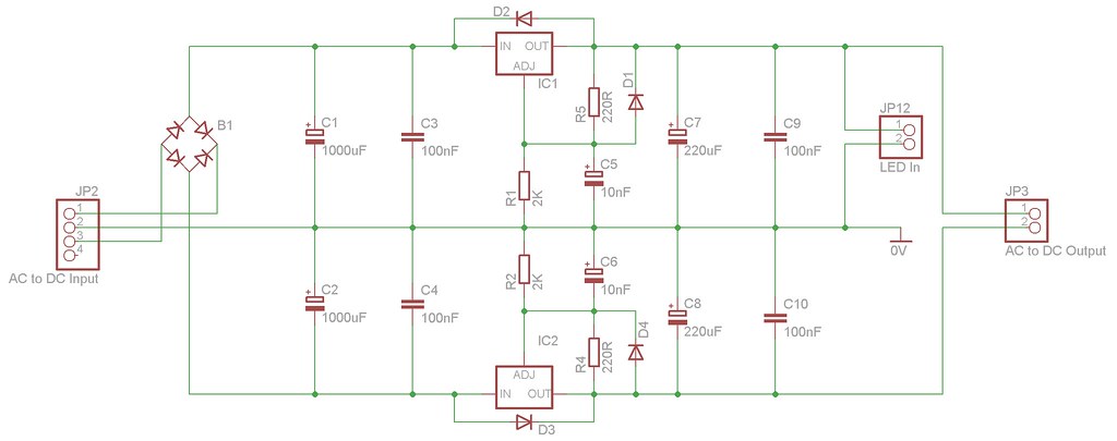
Here is the power supply. JP2 is connected to a 24-0-24 7VA transformer. IC1 is a LM317 and IC2 is a LM337. JP3 should output +/-12.6V.
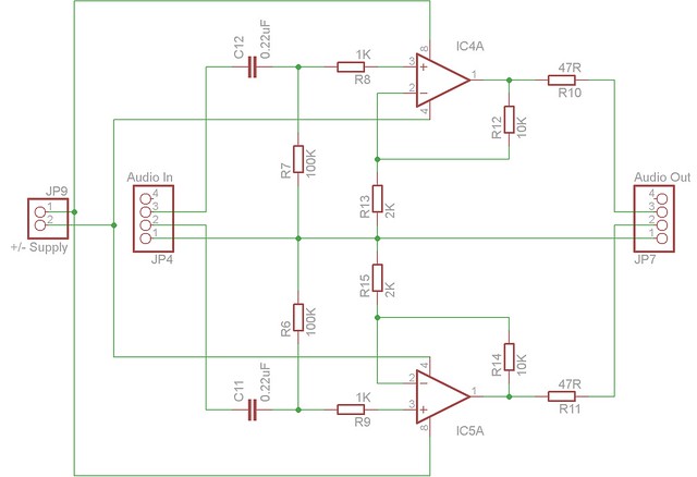
Here is the amplifier. It's using half a OPA2134 for each channel. Each channel has a gain of 6 and should output maximum of 1.8V from an unbalanced line level. The input audio signal at JP4 is adjusted by a 10K Pot.
I've not yet built the design because I wanted to get your thoughts and to check that I haven't done something seriously wrong.
This is my very first project so any feedback at all will be much appreciated. The more honest, the better 🙂
Many Thanks
Stephen
First of all I just want to say Hi. This is an excellent community and I've found everything I read here really helpful. You guys seem really helpful and friendly 🙂
I'm posting today to get your comments and criticisms on a power supply and headphone amplifier that I've designed. I've based the design from quite a few found on this forum and the internet.
Here is the power supply. JP2 is connected to a 24-0-24 7VA transformer. IC1 is a LM317 and IC2 is a LM337. JP3 should output +/-12.6V.
Here is the amplifier. It's using half a OPA2134 for each channel. Each channel has a gain of 6 and should output maximum of 1.8V from an unbalanced line level. The input audio signal at JP4 is adjusted by a 10K Pot.
I've not yet built the design because I wanted to get your thoughts and to check that I haven't done something seriously wrong.
This is my very first project so any feedback at all will be much appreciated. The more honest, the better 🙂
Many Thanks
Stephen
R4 on the 337 does not pass the necessary 10mA for the regulator to perform when the load is nil or very light.
You are relying on the quiescent current of the dual opamp to increase the minimum draw on the 337.
What is the minimum current draw of an opa2134 when it sends AC current to the next stage?
10nF across R1 & R2 seems very low. Most recommend >=10uF and I like 220uF.
C3, 4, 9 & 10 are located in the wrong position. They should all be right next to the regulator pins.
No RF attenuation at the input of the pre-amp.
No decoupling on the opamp power pins.
Gain = 6times (+15.5dB) is unusually high for a line stage. +0dB, +6dB & +12dB are much more common.
Last edited:
Hi Andrew,
The minimum current draw of an opa2134 is 5mA. Will this be enough, if not, how can calculate what the value of R4 should be?
Many Thanks 🙂
Stephen
The minimum current draw of an opa2134 is 5mA. Will this be enough, if not, how can calculate what the value of R4 should be?
Many Thanks 🙂
Stephen
Hi Andrew,
Just seen your edits. Also I have to keep waiting for a moderator to approve my replies since I'm new here.
I used 10nF because it was recommended in the datasheet. Changing this to 220uF would be a bonus since it's one less component to buy.
I shall move those caps 🙂
The input signal is attenuated by a 10K pot and the 1K series resistor.
How critical is decoupling the opamp power pins since the power source will close (inches) to the opamp?
What gain would you recommend?
Many Thanks for your time 🙂
Cheers
Stephen
Hi,
5mA for the whole opa2134 or 5mA for each half?
The problem is very easily solved by changing the four resistors across the regs.
Change the 220r to 100r. That alone will draw 12.5mA, then it does not matter how little the opamps draw.
The problem with the quiescent current, that I can't help you with, is that I don't know what proportion of the quiescent current is running the voltage amp stages and changes very little and what is biased through the ClassAB output stage. When a signal passes, the output bias can drop to zero mA intermittently, That could drive a poor copy of a 337 into instability.
Well I've done some reading about decoupling capacitors and it seems the consensus is to always put one next to the power pins of IC's. I've updated the diagram of both the amp and psu with 100nF caps. I have also changed the 10nF to 10uF. I think that might have been a typo.
Power Supply
Amplifier
I'm still keen to find out what sort of gain would be appropriate for a headphone amplifier based upon 0.316V line level input.
Many Thanks
Stephen
Power Supply
An externally hosted image should be here but it was not working when we last tested it.
Amplifier
An externally hosted image should be here but it was not working when we last tested it.
I'm still keen to find out what sort of gain would be appropriate for a headphone amplifier based upon 0.316V line level input.
Many Thanks
Stephen
What is the gain of the headphone amplifier?
What is the absolute maximum signal voltage to the headphones. Quite a number of my old models specify 5Vpk maximum
What is the sensitivity of the headphones?
Once you take all of that into account you may find that the total gain of the pre-amp and the headphone amp be ~+12dB
What is the absolute maximum signal voltage to the headphones. Quite a number of my old models specify 5Vpk maximum
What is the sensitivity of the headphones?
Once you take all of that into account you may find that the total gain of the pre-amp and the headphone amp be ~+12dB
Hi Andrew,
The gain of the amp at the moment is 6 as mentioned previously. I'm not sure on the full technical specs of the headphones because their not given on the manufactures website. All that I know is that they are 32ohm:
Sennheiser UK - HD 215
Thanks again for your help 🙂
Cheers
Stephen
The gain of the amp at the moment is 6 as mentioned previously. I'm not sure on the full technical specs of the headphones because their not given on the manufactures website. All that I know is that they are 32ohm:
Sennheiser UK - HD 215
Thanks again for your help 🙂
Cheers
Stephen
Here is the power supply. JP2 is connected to a 24-0-24 7VA transformer. IC1 is a LM317 and IC2 is a LM337. JP3 should output +/-12.6V.
That transformer will give more than ±30 V DC. That means each of the voltage regulators must stand a voltage drop of more than 17 V. Even with the low current consumption of a headphone amp that is an unnecessary waste and heat dissipation. A 2x12 V or 2x15 V transformer would be more appropriate.
That transformer will give more than ±30 V DC. That means each of the voltage regulators must stand a voltage drop of more than 17 V. Even with the low current consumption of a headphone amp that is an unnecessary waste and heat dissipation. A 2x12 V or 2x15 V transformer would be more appropriate.
Your quite right... Well spotted 🙂
I can tell you from experience that 6x gain is way too much unless you are using some strange source with a really low output voltage.
If you are using something like an iPod for the source, 3x should be more than you will ever need.
If you are using something like an iPod for the source, 3x should be more than you will ever need.
I'd think about one of these:- http://focus.ti.com/lit/ds/symlink/tpa6120a2.pdf, which is a dedicated headphone amp from TI which has a good reputation.
w
w
I can tell you from experience that 6x gain is way too much unless you are using some strange source with a really low output voltage.
If you are using something like an iPod for the source, 3x should be more than you will ever need.
I'll be using an iPod Touch using a line out cable. Should I aim for 4x gain, this will then give me about 1.2V max at the headphones??
During my research, most headphone amp schematics range from 4x to 6x gain which is the reason I originally went for 6x gain.
Many Thanks
Stephen
I'd think about one of these:- http://focus.ti.com/lit/ds/symlink/tpa6120a2.pdf, which is a dedicated headphone amp from TI which has a good reputation.
w
That's almost perfect, except I not quite ready to venture in to creating my own PCB's and SMD IC's.
At the moment, this headphone amp will be created on 160x108 veroboard.
I'll keep it in mind though for future projects.
Many Thanks
Stephen
Am I getting confused?keen to find out what sort of gain would be appropriate for a headphone amplifier based upon 0.316V line level input.
Is this 2134 the pre-amp or the headamp?
Am I getting confused?
Is this 2134 the pre-amp or the headamp?
It's only the headphone amp. The input will be a line level signal from an iPod and the output will be to a pair of 32ohm headphones.
iPod > Amp > Headphones
🙂
the 2134 has a cold short circuit limit of 40mA and if you look at the graphs you will see that once output current reaches 20mA the performance falls off drastically.
That is 20mApk into your 32ohm headphones, or about 640mVpk, roughly equivalent to 450mVac if they are resistors.
But you need to supply at least two times the current that a resistor demands.
I don't think the 2134 is a suitable candidate for driving 32ohm headphones.
Look again at the datasheet. It shows some data for driving 600r resistors. That gives a clue to the minimum impedance that the 2134 can drive properly.
You need a high current buffer to drive your 32ohm headphones.
Hi Andrew,
I assume that your referring to the very first graph (TOTAL HARMONIC DISTORTION + NOISE vs FREQUENCY)? To me there doesn't look like there would be much difference between 600ohms and 320hms as the amount of gain seems to make the most difference and in any case would be below 0.1% THD+Noise. Would this be audible?
However, what buffer would you recommend? I see a lot of people use the OPA634. Looking at it's datasheet, it has an almost flat frequency response curve when closed-looped at 25ohms which is very near to my headphone impedance.
Many Thanks
Stephen
- Status
- Not open for further replies.
- Home
- Amplifiers
- Chip Amps
- Headphone Amp V-One