I'll be using an iPod Touch using a line out cable. Should I aim for 4x gain, this will then give me about 1.2V max at the headphones??
During my research, most headphone amp schematics range from 4x to 6x gain which is the reason I originally went for 6x gain.
I use 3x with my 32-Ohm cans using an iPod as the source and there is plenty of headroom. You don't want any more gain than you really need. It's best to start low and then change it later if for some reason you find it's not high enough.
I agree that the 2134 is not the best solution for a headphone amp. It's a fun thing to play with as a first circuit, but it's far from being a serious headphone amp.
If you still want to keep things "cmoy-simple", at least look into some of the modern op-amps out there that have higher output current.
Last edited:
Hi All,
I've not yet built the design because I wanted to get your thoughts and to check that I haven't done something seriously wrong.
This is my very first project so any feedback at all will be much appreciated. The more honest, the better 🙂
Many Thanks
Stephen
Where is ground? You connect + and - power from the supply to the opamps but where is the '0' reference point? Change JP3 to a 3 pin connector and bring the power supply ground to the amps. It's also a good idea to have a different number of pins on your connectors so that you don't accidentally connect to the wrong thing. Sometimes it just doesn't work but it really sucks when you let the smoke out because of an avoidable connection error.
Manufacturers often use color coded connectors if they're the same size but that isn't always available for DIYers
G²
You Right! I haven't updated the diagram just yet but I need to after I added the decoupling caps on Vcc+ and Vcc-.
I have 2 questions about grounds though. Do I connect the centre tap ground to the chassis and do I connect the signal ground the the chassis too?
Good tip about the connectors. I might just add some coloured heatshrink around them before soldering them to the board.
Many Thanks
Stephen
I use 3x with my 32-Ohm cans using an iPod as the source and there is plenty of headroom. You don't want any more gain than you really need. It's best to start low and then change it later if for some reason you find it's not high enough.
I agree that the 2134 is not the best solution for a headphone amp. It's a fun thing to play with as a first circuit, but it's far from being a serious headphone amp.
If you still want to keep things "cmoy-simple", at least look into some of the modern op-amps out there that have higher output current.
I would like to keep things simple since it is my first project 🙂
I'll have a look around my local supplier for some other higher output IC's in DIP format and report back.
Many Thanks
Stephen
I'll have a look around my local supplier for some other higher output IC's in DIP format and report back.
DIP is another limitation. A lot of newer op-amps that would be suitable only come in surface mount form factors (and some are only single channel).
Another popular DIP op-amp you could try is the LT1364. It has a minimum output current of 50mA and a short circuit current of 100mA. Just be aware this device is quite a bit faster than the 2134 and will require special attention to layout and bypassing.
You Right! I haven't updated the diagram just yet but I need to after I added the decoupling caps on Vcc+ and Vcc-.
I have 2 questions about grounds though. Do I connect the centre tap ground to the chassis and do I connect the signal ground the the chassis too?
Good tip about the connectors. I might just add some coloured heatshrink around them before soldering them to the board.
Many Thanks
Stephen
You may connect the center tap to the chassis as a shield but don't use the chassis as a conductor. I would tie the center tap to the PC board and use a 10 ohm resistor to tie the signal/power ground to the chassis. The chassis will shield the system but not allow large ground loop currents AND if you ever toast that resistor you'll know something is really wrong.
G²
As an alternative to looking for high-current opamps or buffers, you could consider something like the '47' instead:
HeadWize - Project: Apheared's Project Scrapbook by Michael Shelton
This parallels two opamps to drive more current. You could extend this to use a quad opamp per channel. The 47 ohm resistors ensure that the output current is shared between opamps.
HeadWize - Project: Apheared's Project Scrapbook by Michael Shelton
This parallels two opamps to drive more current. You could extend this to use a quad opamp per channel. The 47 ohm resistors ensure that the output current is shared between opamps.
Anyone have any opinions about the LF356. I don't fully understand everything in these datasheets but the LF356 looks like a good replacement for the OPA2134 to drive 32ohm headphones.
Here is the datasheet: http://www.national.com/ds/LF/LF155.pdf
Here is the datasheet: http://www.national.com/ds/LF/LF155.pdf

Anyone have any opinions about the LF356. I don't fully understand everything in these datasheets but the LF356 looks like a good replacement for the OPA2134 to drive 32ohm headphones.
Here is the datasheet: http://www.national.com/ds/LF/LF155.pdf
Opamps have different speeds, idle currents, output currents and more. The LF356 is nothing special in any of those categories. If you're running on batteries you'd be more interested in low idle currents. If line powered that item is of no concern and you can go for higher output drive capacity though in reality, unless you want it real loud it won't be a problem.
G²
Hi,
a headphone could demand a maximum peak transient current of ~2 to 3 times what the nominal impedance/resistance of the VC.
I don't think headphones without crossovers are as bad at demanding current as 2way and 3way speakers. I'll use 2times as the worst case for headphones.
Starting with a 32ohm VC. It's worst case current demand will be equivalent to a 16r0 resistor.
Let's try to put in 100mW of power to the headphone.
Vpk = sqrt(2 * P * Rload) = sqrt(2 * 0.1 * 16) = 1.79Vpk
Ipk = Vpk / Rpk = 1.79 / 16 = 112mApk.
This shows that to drive a 16ohm resistive load to 100mW, the amplifier should be able to deliver 112mApk while the voltage remains at 1.79Vpk.
While the amplifier is sending 1.79Vpk, equivalent to 1.266Vac, the average power the headphone will receive over it's average impedance of 32ohms is 50mW.
Summarising
a 32ohm headphone with a maximum requirement of 50mW can demand upto 112mApk on loud fast transients.
Hi,
a headphone could demand a maximum peak transient current of ~2 to 3 times what the nominal impedance/resistance of the VC.
I don't think headphones without crossovers are as bad at demanding current as 2way and 3way speakers. I'll use 2times as the worst case for headphones.
Starting with a 32ohm VC. It's worst case current demand will be equivalent to a 16r0 resistor.
Let's try to put in 100mW of power to the headphone.
Vpk = sqrt(2 * P * Rload) = sqrt(2 * 0.1 * 16) = 1.79Vpk
Ipk = Vpk / Rpk = 1.79 / 16 = 112mApk.
This shows that to drive a 16ohm resistive load to 100mW, the amplifier should be able to deliver 112mApk while the voltage remains at 1.79Vpk.
While the amplifier is sending 1.79Vpk, equivalent to 1.266Vac, the average power the headphone will receive over it's average impedance of 32ohms is 50mW.
Summarising
a 32ohm headphone with a maximum requirement of 50mW can demand upto 112mApk on loud fast transients.
That was an excellent piece of information 🙂 I really appreciate the the theory. Definitely help choosing components.
I'm starting to lean toward the BUF634 as a buffer stage which has high current, 250mA, and high bandwidth.
If no one can see any problems with using a OPA2134 then a BUF634, then my next job will be to find a UK supplier with a reasonable price tag........
Many Thanks
Stephen
you must read Walt Jung before ordering parts.
He details, extensively, the design of composite opamp amplifiers.
He details, extensively, the design of composite opamp amplifiers.
signal gnd = feedback gnd = load gnd
also you can save 1/3 on amplifier parts/cost while improving performance and efficency by dropping the "3-channel" output gnd when you're building a perfectly fine dual supply
only if you wanted to use a single supply "wall wart" or battery supply is active gnd then useful - but properly used it is not "3-channel" as cooked up by the Head-Fi folks - they're just plain wrong
The Pimeta’s "3-channel" topology is fundamentally flawed - most technical reasons given for it are simply not true or can be bettered by proper layout
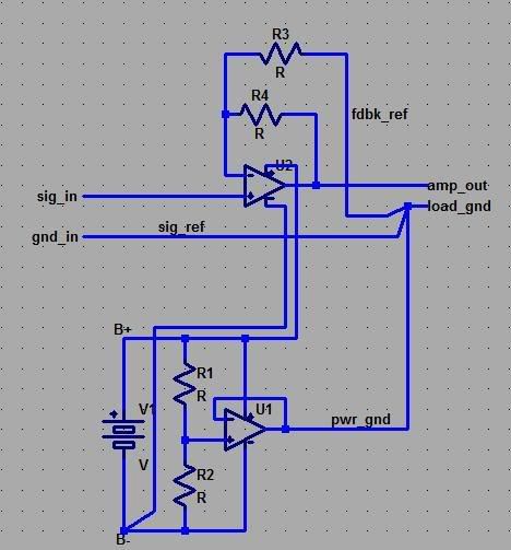
"active supply splitter" can be useful when wanting to use single V supply - the single active gnd should be used for input, feedback and load gnd
but "3-channel" puts the gnd “buffer” amp in series with the load - with the input and feedback grounds separated from the load gnd - this means all of the error of the "output gnd" buffer is in series with the headphones - giving distortion and "output gnd" impedance crosstalk that is worse than with a good "passive" gnd of heavy conductor with signal input gnd, feedback gnd "star" connected with the load common ground pin of the TRS connector
A "active gnd" showing star at output - can better "3-channel" performance:
...
Last edited:

- Status
- Not open for further replies.
- Home
- Amplifiers
- Chip Amps
- Headphone Amp V-One