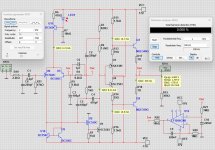
I am planning to make a headphone amplifier based on LIneUp's Nawaho design.
The basic change is the BTJ output stage.
The first simulations with KSA1381 / KSC 3505 transistors at the output (all the same)
First sims are promising - distortion, stability (olg), squarewave are good.
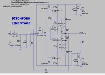
I am thinking about the PCB design and I have an idea that worked perfectly for me with the headphone version of the Cello amplifier
A dual-mono design with two independent stabilizers, two transformers and only one common ground point - on the headphone socket
The power supplies are also based on the Lineup design
Proven in several projects and work great
What do you think about this design?
Do you have any suggestions?
Regards
The basic change is the BTJ output stage.
The first simulations with KSA1381 / KSC 3505 transistors at the output (all the same)
First sims are promising - distortion, stability (olg), squarewave are good.
I am thinking about the PCB design and I have an idea that worked perfectly for me with the headphone version of the Cello amplifier
A dual-mono design with two independent stabilizers, two transformers and only one common ground point - on the headphone socket
The power supplies are also based on the Lineup design
Proven in several projects and work great
What do you think about this design?
Do you have any suggestions?
Regards

You are a clever builder. So it will work great.
How much bias do you get in output?
300/600 Ohm headphones does not need much current.
I say even 50 mA will do.
The output transistors can only take max 100 mA!
The gain is set to 5.5.
It will be perfect.
How much bias do you get in output?
300/600 Ohm headphones does not need much current.
I say even 50 mA will do.
The output transistors can only take max 100 mA!
The gain is set to 5.5.
It will be perfect.
KSC3503/KSA1381 can only take 100 mA.
So to be safe you need to set it max 75 mA.
Or use BD139/BD140 or MJE340/MJE350
So to be safe you need to set it max 75 mA.
Or use BD139/BD140 or MJE340/MJE350
@ZoltanChivay
I setup your circuit in my SPICE. I used MJE340/350 for output. Bias in your circuit read 103mA.
It works well.
Changes that I want to make:
R20 = 18k, as noted
C3 = 150pF
C3 is a part of TMC compensation. When using lower circuit gain the comp can need adjustment.
For lowest distortion I used 150pF instead of 100pF.
Result THD 0.000052%
-----
edit:
Actually for optimal value C3 should be 180pF
Result THD 0.000047%
Last edited:
I am still wondering about the choice of transistors
The problem I see is that popular BC and MJE type transistors have several different manufacturers( Philips Motorola and many no-name ...) = differences in sound
I think that if we want to build a decent amplifier, we cannot allow for such differences because then each builder will have a slightly different amplifier.
IMO the amplifier topology will allow for good sound, further design assumptions such as full dual-mono, stabilized power supply will help us build a really serious headphone amplifier
We should choose proven, trusted transistors available from proven suppliers such as Mouser etc.
Personally, I lean towards OnSemi and Toshiba transistors
Small-signal are KSA992 / KSC1845 (I have good experience with them), output are TTA004B / TTC004B
They are available, they are not EOL and they are relatively cheap
And I will probably design a board on such transistors to make a prototype.
KSC1845 and KSA992 I have in SPICE.
And of course KSC3503 and KSA1381.
But TTC004B and TTA004B I have not.
But the output devices are not as important as the input and VAS.
The amplifier is controlled by the input stages.
And of course KSC3503 and KSA1381.
But TTC004B and TTA004B I have not.
But the output devices are not as important as the input and VAS.
The amplifier is controlled by the input stages.
@lineup TTA004B and TTC004B
*********************************************************************
*********************************************************************
- (C) Copyright TOSHIBA CORPORATION 2016
- Date :21/08/2016
- File Name :TTA004B.lib
- Part Number :TTA004B
- Parameter Ver. :Ver.2
- Simulator 😛Spice
- Model Call Name :TTA004B
- TNOM :25 degree
- Pin Assign :1=Collector 2=Base 3=Emitter
.SUBCKT TTA004B 1 2 3
Q1 1 2 3 3 TTA004B_BJT
.MODEL TTA004B_BJT PNP(
.ENDS
- LEVEL = 1
- TNOM = 25
- IS = 7.5e-014
- BF = 190
- IKF = 0.47
- ISE = 5e-011
- NE = 2.4
- NK = 0.63
- XTB = 1
- XTI = 2
- TRC1 = 0.003
- NF = 1
- VAF = 6.8
- VAR = 50
- BR = 6
- IKR = 5
- ISC = 1.0e-21
- NR = 1.015
- NC = 1
- RB = 4
- RC = 0.125
- RE = 0.05
- CJC = 4.09E-011
- MJC = 0.33
- VJC = 0.75
- CJE = 1e-11
- MJE = 0.33
- VJE = 0.75
- EG = 1.11
- TR = 1E-009
- TF = 1.59E-009)
*********************************************************************
*********************************************************************
- (C) Copyright TOSHIBA CORPORATION 2016
- Date :05/08/2016
- File Name :TTC004B.lib
- Part Number :TTC004B
- Parameter Ver. :Ver.1
- Simulator 😛Spice
- Model Call Name :TTC004B
- TNOM :25 degree
- Pin Assign :1=Collector 2=Base 3=Emitter
.SUBCKT TTC004B 1 2 3
Q1 1 2 3 3 TTC004B_BJT
.MODEL TTC004B_BJT NPN(
.ENDS
- LEVEL = 1
- TNOM = 25
- IS = 1.374e-013
- BF = 137.2
- NF = 1
- VAF = 11.95
- IKF = 0.5057
- ISE = 8.098e-013
- NE = 1.8
- BR = 35.11
- NR = 1
- VAR = 1000
- IKR = 10
- ISC = 1.916e-011
- NC = 1.5
- NK = 0.55
- RE = 0.115
- RB = 0.885
- RC = 0.0709
- CJE = 5.78E-011
- VJE = 0.75
- MJE = 0.33
- CJC = 2.89E-011
- VJC = 0.75
- MJC = 0.33
- FC = 0.5
- TF = 1.545E-009
- XTF = 1
- VTF = 1
- ITF = 1
- PTF = 0
- TR = 0
- EG = 1.11
- XTB = 1.4
- XTI = 6.467)
thanks @mz543578854
🙂
------
edit:
But unfortunately there was 70 errors! when I ran TTC004B.
But if I ran it anyway and discarded the errors warning it worked somehow.
🙂
------
edit:
But unfortunately there was 70 errors! when I ran TTC004B.
But if I ran it anyway and discarded the errors warning it worked somehow.
Last edited:
Here is the master model text I use on all my simulations.
Wolverine team uses it , most of DIYA uses it. Works with LT.
OS
I can even paste the raw text below into the "body" of the simulation.
If this is already in the text - "multiple models for xxxx found" message will appear.
.MODEL TTA004B_BJT PNP
.MODEL TTC004B_BJT NPN
Wolverine team uses it , most of DIYA uses it. Works with LT.
OS
I can even paste the raw text below into the "body" of the simulation.
If this is already in the text - "multiple models for xxxx found" message will appear.
.MODEL TTA004B_BJT PNP
- LEVEL = 1
- TNOM = 25
- IS = 7.5e-014
- BF = 190
- IKF = 0.47
- ISE = 5e-011
- NE = 2.4
- NK = 0.63
- XTB = 1
- XTI = 2
- TRC1 = 0.003
- NF = 1
- VAF = 6.8
- VAR = 50
- BR = 6
- IKR = 5
- ISC = 1.0e-21
- NR = 1.015
- NC = 1
- RB = 4
- RC = 0.125
- RE = 0.05
- CJC = 4.09E-011
- MJC = 0.33
- VJC = 0.75
- CJE = 1e-11
- MJE = 0.33
- VJE = 0.75
- EG = 1.11
- TR = 1E-009
- TF = 1.59E-009
.MODEL TTC004B_BJT NPN
- LEVEL = 1
- TNOM = 25
- IS = 1.374e-013
- BF = 137.2
- NF = 1
- VAF = 11.95
- IKF = 0.5057
- ISE = 8.098e-013
- NE = 1.8
- BR = 35.11
- NR = 1
- VAR = 1000
- IKR = 10
- ISC = 1.916e-011
- NC = 1.5
- NK = 0.55
- RE = 0.115
- RB = 0.885
- RC = 0.0709
- CJE = 5.78E-011
- VJE = 0.75
- MJE = 0.33
- CJC = 2.89E-011
- VJC = 0.75
- MJC = 0.33
- FC = 0.5
- TF = 1.545E-009
- XTF = 1
- VTF = 1
- ITF = 1
- PTF = 0
- TR = 0
- EG = 1.11
- XTB = 1.4
- XTI = 6.467
Attachments
thanks very much
TTC004B tested from your supplied file @ostripper
And it works. No errors.
I do use Multisim and not LTspice.
TTC004B tested from your supplied file @ostripper
And it works. No errors.
I do use Multisim and not LTspice.
Very good devices , Toshiba's .... Regulators , pre-drivers , VAS's. Perfect !
The models emulate the real world devices perfectly.
I started using them as the 2sc3503/2sa1381's are obsolete and harder to find.
Now I use 2SA1419S-TD-E / 2SC3649S-TD-E SMD to go fully "21'st century"
OS
The models emulate the real world devices perfectly.
I started using them as the 2sc3503/2sa1381's are obsolete and harder to find.
Now I use 2SA1419S-TD-E / 2SC3649S-TD-E SMD to go fully "21'st century"
OS
Last edited:
What I did not recognize when pasting yesterday is that Toshiba wrapped in a .SUBCKT. Not sure if that could have caused your issues.edit:
But unfortunately there was 70 errors! when I ran TTC004B.
But if I ran it anyway and discarded the errors warning it worked somehow.
Looking at the values, the models ostripper posted seem to be identical.
- Home
- Amplifiers
- Headphone Systems
- Headphone amp based on LineUp's Navaho amplifier